Community project
I M Building Test-phase Prototype Of Capstone Co
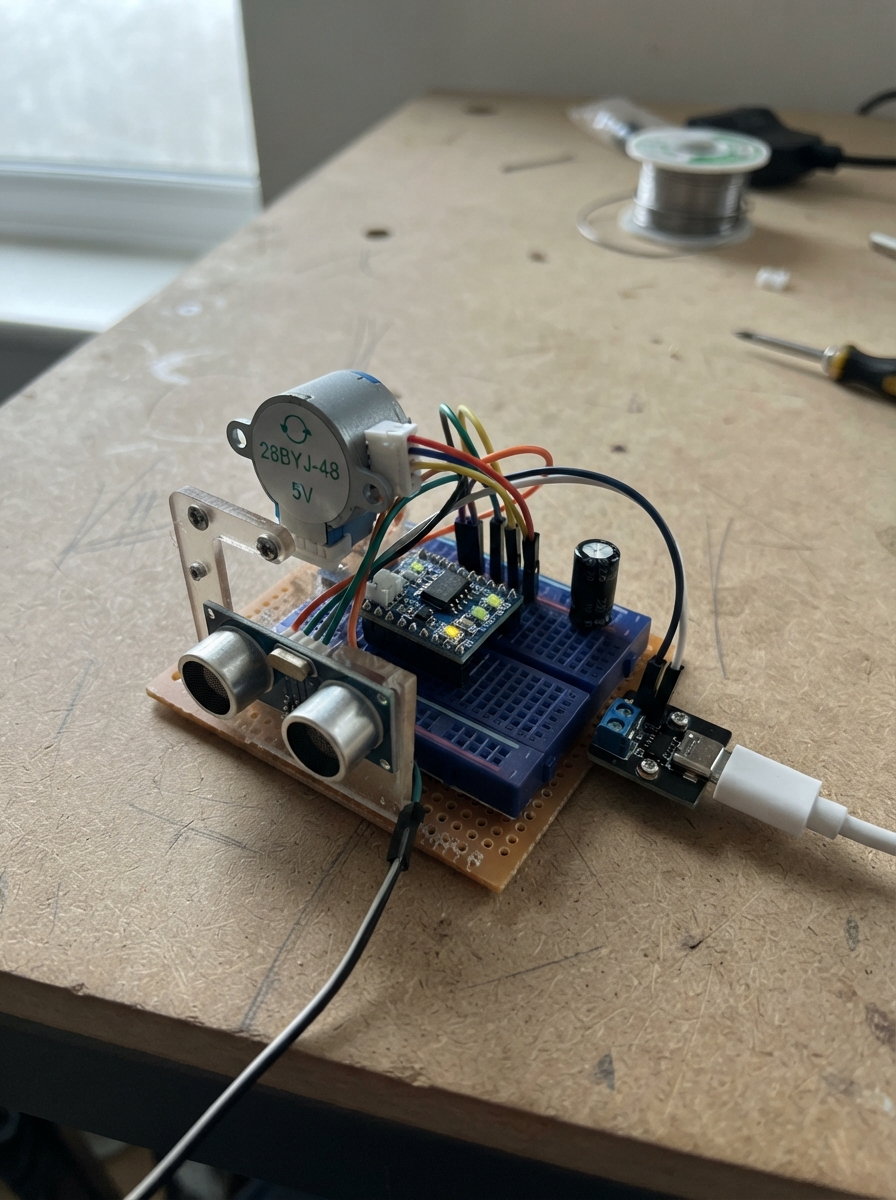
This guide walks through building a test-phase prototype of a single-lane conveyor dispenser system controlled by an Arduino Uno. The system uses a 28BYJ-48 stepper motor to advance packages along a conveyor belt and an HC-SR04 ultrasonic sensor to detect package presence and spacing. Builders will receive a complete wiring diagram, parts list, and step-by-step assembly instructions that culminate in three validation tests: sensor-only bench verification, belt-only motion tuning, and full dispense reliability testing.
The firmware provides serial commands for manual dispense triggering, package return logging, sensor calibration, and system diagnostics. Key mechanical parameters—package spacing and roller diameter—are easily tuned via constants and EEPROM storage, allowing the prototype to adapt to different conveyor configurations. This guide is ideal for makers prototyping automated material handling or learning stepper motor control with real-world feedback from distance sensing.
Wiring diagram

Gather all the parts
Assemble it in 10 steps
1. Gather the single-lane parts
Use one Arduino Uno, one 28BYJ-48 motor with its ULN2003 board, one HC-SR04 sensor, a 220 µF capacitor rated 10 V or higher, a regulated 5 V supply rated at least 2 A, breadboard, jumper wires, and your belt lane. The motor, belt, drive roller, idle roller, chute, and package guides form the mechanical lane.
- Measure the actual belt-contact diameter of the driven roller with calipers or a ruler; do not use the motor shaft diameter.
- Use packages with one fixed size and a fixed centre-to-centre spacing for this test.
- Do not use the Uno USB connection as the motor power source; the small motor can cause resets or overheat the board connection.
2. Build and align the conveyor lane
Mount the motor so its output shaft drives one roller. Fit the belt with enough tension that it does not slip but can still be turned by hand. Mount the free roller at the far end. Add side guides so packages stay single-file, set their centres one fixed spacing apart, and place the chute immediately after the front roller.
- Mark one belt position with tape so you can measure movement accurately during the motor test.
- Make the drop end clear: a package should fall without rubbing a guide or the roller.
- Keep fingers, loose clothing, and wires away from the rollers while the motor is powered.
3. Mount the distance sensor at the rear
Mount the HC-SR04 at the rear of the lane, opposite the chute, aimed straight along the package row at the flat rear face of the rearmost package. Keep the nearest target at least 20 mm away and add simple matte side shrouds only if needed to block echoes from the walls.
- The sensor beam spreads by roughly 15 degrees, so make the package face fill the beam before the belt rails or walls do.
- Avoid shiny angled package surfaces; a flat, matte target face gives steadier readings.
- If the beam sees the belt frame or a wall instead of the package, distance changes cannot reliably confirm a dispense.
4. Connect the motor and driver
Plug the 28BYJ-48 five-wire plug into the matching socket on the ULN2003 board. Connect ULN2003 IN1 to Uno D8 (motor signal), IN2 to D9 (motor signal), IN3 to D10 (motor signal), and IN4 to D11 (motor signal). Connect ULN2003 + to the shared 5 V rail (motor power) and ULN2003 - to the shared GND rail (ground).
- Use four differently colored wires for IN1 through IN4 so they are easy to trace.
- The motor plug is keyed; do not force it.
5. Connect the ultrasonic sensor
Connect HC-SR04 VCC to the shared 5 V rail (power), GND to the shared GND rail (ground), TRIG to Uno D2 (send signal), and ECHO to Uno D3 (return signal).
- Keep the sensor wires away from the moving belt and rollers.
- The Uno accepts the HC-SR04 ECHO signal directly because both use 5 V logic.
- Make sure VCC and GND are not swapped — swapped power can damage the sensor.
6. Add the power supply and smoothing capacitor
Connect the supply +5V to the shared 5 V rail, then run that rail to the Uno 5V pin and the ULN2003 + pin. Connect supply GND to the shared ground rail, then run it to Uno GND and ULN2003 -. Place the 220 µF capacitor across the ULN2003 power input: its long positive lead to +5 V and its striped negative lead to GND.
- Use short, thicker wires for the supply-to-driver connections.
- The Uno USB cable may remain plugged in for Serial logging, but use the external regulated 5 V rail for motor power.
- The capacitor is polarized: reversing it can make it heat, leak, or fail.
- Before applying power, confirm the external supply is regulated 5 V, not 9 V or 12 V.
7. Set the initial firmware constants
Before deployment, edit PACKAGE_SPACING_MM to the measured centre-to-centre package spacing, DRIVEN_ROLLER_DIAMETER_MM to the measured belt-contact diameter, and STARTING_PACKAGE_COUNT to the number in a full row. The included 20 mm spacing, 20 mm roller, and 10-package values are examples only. The code calculates the theoretical starting value in its header, but tune STEPS_PER_SPACING from the belt measurement in the next step.
- For a 20 mm driven roller and 20 mm spacing, the theoretical start is about 1304 half-steps: 4096 × 20 ÷ (pi × 20).
- Leave DISTANCE_TOLERANCE_MM at 7 mm initially, then tighten it only after stable measurements.
8. Run the sensor-only bench test
Keep the motor stopped. With a full row installed, press Deploy and open the Serial view at 115200 baud. Send S five times and record the reported distance. Remove every package without changing the sensor or belt, then send S five times again. The readings should be steady enough that the full and empty groups do not overlap. Send C, then follow the Serial prompts: send F with the full row installed and E with the lane empty.
- The firmware takes seven readings and uses the middle one, which ignores a few bad echoes.
- Repeat this setup if a reading is below 20 mm, times out, or changes greatly while nothing moves.
- Do not calibrate with a hand in the beam; calibrate using the real package face and the normal empty belt.
9. Run the belt-only motion test
With the lane clear, put a tape mark on the belt and a fixed reference mark on the frame. Run T once to check that the belt visibly pulses. Then temporarily command a known multiple of STEPS_PER_SPACING, measure the belt movement in millimetres, and adjust STEPS_PER_SPACING by multiplying its old value by target movement divided by measured movement. Repeat until one command moves exactly one package spacing.
- Measure over 5 to 10 spacing moves and divide by the number of moves; this reduces ruler error.
- If the motor chatters or misses motion, increase STEP_DELAY_US before increasing the step count.
- Never tune by changing only the package count; correct the belt movement first.
10. Run the full dispense reliability test
Reload the calibrated full row. For each trial, record the distance before and after a D command, observe whether exactly one package falls, and compare the firmware count to the real count. Perform 30 to 50 dispense trials, reloading as needed. CSV lines are already printed as timestamp_ms,event,steps_commanded,distance_mm,count_estimate,status; paste them into a spreadsheet after the run.
- Use the test columns: trial number, expected result, actual result, dispense success Y/N, distance before, distance after, expected increase, actual increase, count estimate, actual count, error/notes.
- Calculate dispensing success rate = successful one-package drops ÷ total D commands × 100. Calculate counting accuracy = trials where count estimate equals actual count ÷ trials × 100.
- Stop the test if a package jams, two packages move together, or the sensor reading changes without a package movement; correct the physical cause before collecting more data.
Review all connections
1. Connections between "supply_5v" and "Arduino"
2. Connections between "uln2003_1" and "Arduino"
3. Connections between "ultrasonic_1" and "Arduino"
4. Connections between "motor_capacitor_1" and "Arduino"
Deploy the firmware
#include <Arduino.h>
#include <EEPROM.h>

/*
  One-lane conveyor dispenser test prototype — Arduino Uno
  Serial: 115200 baud. Commands: D=dispense, R=returned package,
  C=calibrate, S=status, T=self-test.

  THEORETICAL STARTING STEP CALCULATION:
  28BYJ-48 output (half-step) ≈ 4096 steps/revolution.
  Roller circumference = PI × driven roller diameter.
  Steps per package spacing = 4096 × package spacing / roller circumference.
  Example: 20 mm spacing, 20 mm belt-contact roller diameter:
  4096 × 20 / (PI × 20) = about 1304 half-steps.
  Use the belt-only test to tune STEPS_PER_SPACING. Belt slip and roller
  tolerance mean measured movement is more important than this estimate.
*/

// ---------- EASY-TO-TUNE MECHANICAL AND DECISION CONSTANTS ----------

struct CalibrationData {
  uint16_t magic;
  float fullDistanceMm;
  float emptyDistanceMm;
  float expectedIncreaseMm;
};


// Forward declarations
void logEvent(const char *eventName, long steps, float distanceMm, const char *status);
void setMotorPattern(int index);
void releaseMotor();
void moveMotor(long requestedSteps);
float oneDistanceReadingMm();
float medianDistanceMm();
bool calibrationValid();
bool isEmptyDistance(float distanceMm);
void printStatus();
void runCalibration();
void dispenseOne();
void recordReturn();
void selfTest();

const float PACKAGE_SPACING_MM = 20.0;       // Replace with actual fixed package spacing.
const float DRIVEN_ROLLER_DIAMETER_MM = 20.0; // Belt-contact diameter, not motor shaft diameter.
const long MOTOR_STEPS_PER_OUTPUT_REV = 4096; // 28BYJ-48 half-step approximation.
const long STEPS_PER_SPACING = 1304;          // Tune after belt measurement.
const long MAX_STEPS_PER_DISPENSE = 2608;     // One move plus exactly one retry.
const byte STARTING_PACKAGE_COUNT = 10;       // Full-lane count used during calibration.
const byte LOW_STOCK_THRESHOLD = 3;
const float DISTANCE_TOLERANCE_MM = 7.0;      // Allowed error around expected increase.
const float EMPTY_TOLERANCE_MM = 12.0;        // Near-empty calibration distance allowance.
const unsigned int STEP_DELAY_US = 1800;      // Increase if the motor buzzes or skips.
const byte MEDIAN_SAMPLES = 7;
const unsigned long ECHO_TIMEOUT_US = 30000UL;
const long SELF_TEST_STEPS = 32;

// ---------- PIN DEFINITIONS: REVIEWED AGAINST THE WIRING DIAGRAM (connector verified) ----------
const byte TRIG_PIN = 2;
const byte ECHO_PIN = 3;
const byte IN1_PIN = 8;
const byte IN2_PIN = 9;
const byte IN3_PIN = 10;
const byte IN4_PIN = 11;


const uint16_t EEPROM_MAGIC = 0xC48D;
CalibrationData calibration;
int countEstimate = STARTING_PACKAGE_COUNT;
long totalCommandedSteps = 0;
int stepIndex = 0;

const byte halfStepPattern[8][4] = {
  {1, 0, 0, 0}, {1, 1, 0, 0}, {0, 1, 0, 0}, {0, 1, 1, 0},
  {0, 0, 1, 0}, {0, 0, 1, 1}, {0, 0, 0, 1}, {1, 0, 0, 1}
};

void logEvent(const char *eventName, long steps, float distanceMm, const char *status) {
  Serial.print(millis()); Serial.print(',');
  Serial.print(eventName); Serial.print(',');
  Serial.print(steps); Serial.print(',');
  if (distanceMm < 0) Serial.print("NA"); else Serial.print(distanceMm, 1);
  Serial.print(','); Serial.print(countEstimate); Serial.print(',');
  Serial.println(status);
}

void setMotorPattern(int index) {
  digitalWrite(IN1_PIN, halfStepPattern[index][0]);
  digitalWrite(IN2_PIN, halfStepPattern[index][1]);
  digitalWrite(IN3_PIN, halfStepPattern[index][2]);
  digitalWrite(IN4_PIN, halfStepPattern[index][3]);
}

void releaseMotor() {
  digitalWrite(IN1_PIN, LOW); digitalWrite(IN2_PIN, LOW);
  digitalWrite(IN3_PIN, LOW); digitalWrite(IN4_PIN, LOW);
}

void moveMotor(long requestedSteps) {
  for (long i = 0; i < requestedSteps; i++) {
    stepIndex = (stepIndex + 1) & 7;
    setMotorPattern(stepIndex);
    delayMicroseconds(STEP_DELAY_US);
  }
  totalCommandedSteps += requestedSteps;
  releaseMotor(); // Prevents unnecessary heating while stopped.
}

float oneDistanceReadingMm() {
  digitalWrite(TRIG_PIN, LOW); delayMicroseconds(3);
  digitalWrite(TRIG_PIN, HIGH); delayMicroseconds(10);
  digitalWrite(TRIG_PIN, LOW);
  unsigned long duration = pulseIn(ECHO_PIN, HIGH, ECHO_TIMEOUT_US);
  if (duration == 0) return -1.0;
  return duration * 0.343f / 2.0f;
}

float medianDistanceMm() {
  float readings[MEDIAN_SAMPLES];
  byte valid = 0;
  for (byte i = 0; i < MEDIAN_SAMPLES; i++) {
    float reading = oneDistanceReadingMm();
    if (reading >= 20.0 && reading <= 4000.0) readings[valid++] = reading;
    delay(45); // Wait so echoes from one sample do not affect the next.
  }
  if (valid < (MEDIAN_SAMPLES / 2 + 1)) return -1.0;
  for (byte i = 0; i < valid; i++) {
    for (byte j = i + 1; j < valid; j++) {
      if (readings[j] < readings[i]) {
        float swapValue = readings[i]; readings[i] = readings[j]; readings[j] = swapValue;
      }
    }
  }
  return readings[valid / 2];
}

bool calibrationValid() {
  return calibration.magic == EEPROM_MAGIC &&
         calibration.emptyDistanceMm > calibration.fullDistanceMm &&
         calibration.expectedIncreaseMm > 0.5;
}

bool isEmptyDistance(float distanceMm) {
  return calibrationValid() && distanceMm >= calibration.emptyDistanceMm - EMPTY_TOLERANCE_MM;
}

const char *stockStatus(float distanceMm) {
  if (countEstimate <= 0 || isEmptyDistance(distanceMm)) return "EMPTY";
  if (countEstimate <= LOW_STOCK_THRESHOLD) return "LOW_STOCK";
  return "OK";
}

void printStatus() {
  float distance = medianDistanceMm();
  logEvent("STATUS", totalCommandedSteps, distance,
           calibrationValid() ? stockStatus(distance) : "UNCALIBRATED");
}

void runCalibration() {
  Serial.println("# CALIBRATION: install a full row of exactly STARTING_PACKAGE_COUNT packages. Send F.");
  while (!Serial.available()) delay(10);
  char input = toupper(Serial.read());
  if (input != 'F') {
    logEvent("CALIBRATION_ABORTED", 0, -1, "EXPECTED_F");
    return;
  }

  float full = medianDistanceMm();
  if (full < 0) {
    logEvent("CALIBRATION_FAILED", 0, full, "FULL_SENSOR_ERROR");
    return;
  }

  Serial.println("# CALIBRATION: remove every package; leave the normal empty belt. Send E.");
  while (!Serial.available()) delay(10);
  input = toupper(Serial.read());
  if (input != 'E') {
    logEvent("CALIBRATION_ABORTED", 0, -1, "EXPECTED_E");
    return;
  }

  float empty = medianDistanceMm();
  if (empty < 0 || empty <= full + 1.0) {
    logEvent("CALIBRATION_FAILED", 0, empty, "EMPTY_READING_INVALID");
    return;
  }

  calibration.magic = EEPROM_MAGIC;
  calibration.fullDistanceMm = full;
  calibration.emptyDistanceMm = empty;
  calibration.expectedIncreaseMm = (empty - full) / STARTING_PACKAGE_COUNT;
  EEPROM.put(0, calibration);
  countEstimate = STARTING_PACKAGE_COUNT;
  logEvent("CALIBRATION_OK", 0, full, "CALIBRATED");
  Serial.print("# full_mm="); Serial.print(full, 1);
  Serial.print(" empty_mm="); Serial.print(empty, 1);
  Serial.print(" expected_increase_mm="); Serial.println(calibration.expectedIncreaseMm, 2);
}

void dispenseOne() {
  if (!calibrationValid()) {
    logEvent("DISPENSE_REJECTED", 0, -1, "CALIBRATE_FIRST");
    return;
  }

  float before = medianDistanceMm();
  if (before < 0) {
    logEvent("DISPENSE_FAILED", 0, before, "SENSOR_ERROR_BEFORE");
    return;
  }
  if (isEmptyDistance(before) || countEstimate <= 0) {
    countEstimate = 0;
    logEvent("DISPENSE_REJECTED", 0, before, "EMPTY");
    return;
  }

  long sentThisCommand = 0;
  for (byte attempt = 0; attempt < 2; attempt++) {
    if (sentThisCommand + STEPS_PER_SPACING > MAX_STEPS_PER_DISPENSE) {
      logEvent("DISPENSE_FAILED", sentThisCommand, before, "MAX_STEP_LIMIT");
      return;
    }

    moveMotor(STEPS_PER_SPACING);
    sentThisCommand += STEPS_PER_SPACING;
    delay(150);

    float after = medianDistanceMm();
    if (after < 0) {
      logEvent("DISPENSE_FAILED", sentThisCommand, after, "SENSOR_ERROR_AFTER");
      return;
    }

    float increase = after - before;
    if (fabs(increase - calibration.expectedIncreaseMm) <= DISTANCE_TOLERANCE_MM) {
      if (countEstimate > 0) countEstimate--;
      logEvent(attempt == 0 ? "DISPENSE_SUCCESS" : "DISPENSE_SUCCESS_RETRY",
               sentThisCommand, after, stockStatus(after));
      Serial.print("# distance_before_mm="); Serial.print(before, 1);
      Serial.print(" actual_increase_mm="); Serial.println(increase, 1);
      return;
    }
  }

  float finalDistance = medianDistanceMm();
  logEvent("DISPENSE_FAILED", sentThisCommand, finalDistance,
           "NO_EXPECTED_DISTANCE_CHANGE");
}

void recordReturn() {
  if (countEstimate < STARTING_PACKAGE_COUNT) countEstimate++;
  float distance = medianDistanceMm();
  logEvent("RETURN_RECORDED", 0, distance,
           calibrationValid() ? stockStatus(distance) : "UNCALIBRATED");
}

void selfTest() {
  float distance = medianDistanceMm();
  logEvent("SELFTEST_SENSOR", 0, distance, distance >= 20.0 ? "PASS" : "FAIL");
  moveMotor(SELF_TEST_STEPS);
  // No encoder exists: confirm actual belt movement with your eyes.
  logEvent("SELFTEST_MOTOR_PULSE", SELF_TEST_STEPS, distance,
           "PASS_VISUALLY_VERIFY_BELT_MOVED");
}

void setup() {
  pinMode(TRIG_PIN, OUTPUT); pinMode(ECHO_PIN, INPUT);
  pinMode(IN1_PIN, OUTPUT); pinMode(IN2_PIN, OUTPUT);
  pinMode(IN3_PIN, OUTPUT); pinMode(IN4_PIN, OUTPUT);
  releaseMotor();
  Serial.begin(115200);
  EEPROM.get(0, calibration);
  Serial.println("timestamp_ms,event,steps_commanded,distance_mm,count_estimate,status");
  logEvent("BOOT", 0, -1, calibrationValid() ? "CALIBRATED" : "UNCALIBRATED_SEND_C");
}

void loop() {
  if (!Serial.available()) return;
  char command = toupper(Serial.read());
  if (command == '\n' || command == '\r' || command == ' ') return;

  switch (command) {
    case 'D': dispenseOne(); break;
    case 'R': recordReturn(); break;
    case 'C': runCalibration(); break;
    case 'S': printStatus(); break;
    case 'T': selfTest(); break;
    default: logEvent("UNKNOWN_COMMAND", 0, -1, "USE_D_R_C_S_T"); break;
  }
}
Remix this project
Make it yours in one click
Open a full copy of this project in your own Schematik workspace — diagram, code, parts, and assembly steps included. Swap the sensor, add features, or redesign the whole thing with AI. The author's original stays untouched.
Related projects
Reloj Digital Con Temporizador
Arduino · September 27, 2026Ricardo Sprovieri
Ultrasonic Distance Alarm
Arduino · September 26, 2026Djimini3 Normal
Necesito Hacer Un Circuito De Un Oxiometro Con
Arduino · September 25, 2026MARIA PAULA LAMBOGLIA VARGAS