Community project
Interactive Robot Head
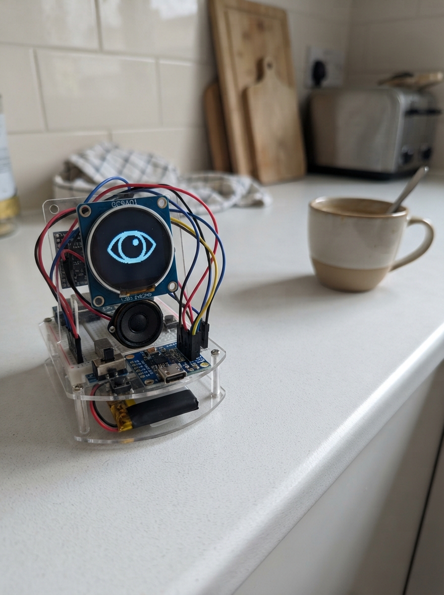
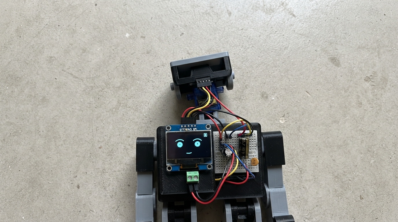
Build an interactive robot head with a round 1.28-inch display, text-to-speech audio output, and personality traits that evolve based on user interaction. The ESP32 microcontroller drives a colorful animated face on the GC9A01 LCD while the MAX98357A amplifier delivers synthesized speech through an 8Ω speaker, all powered by a rechargeable lithium battery with USB charging.
This guide provides a complete wiring diagram, parts list, and step-by-step assembly instructions using a half-size breadboard as the main circuit board. The included Arduino firmware implements facial animations, speech synthesis, and an autonomous mood system with button controls and a mute switch. Test the project over USB before adding the battery to ensure all connections are solid.
Wiring diagram

Gather all the parts
Assemble it in 7 steps
1. Use only the half-size breadboard
Use your 400-tie-point half-size breadboard only. It has about 30 numbered columns and a long centre slot running from one short end to the other. Do not use, buy, or copy a full-size breadboard layout. Push the ESP32 across that long centre slot, with one row of ESP32 pins on each side of the slot and the USB-C connector pointing toward a short edge.
- The ESP32 is the only part that needs to plug into the half-size breadboard.
- Leave the round screen, amplifier, speaker, battery, and charger module on the table around the breadboard.
- Do not put both rows of ESP32 pins into the same connected strip; that would join pins together and can damage the board.
2. Keep the round face screen outside the breadboard
Place the round GC9A01 screen to the left of the half-size breadboard. It stays outside the breadboard. Connect its wires directly to the ESP32: VCC to 3V3 (power), GND to GND (ground), SCK to GPIO18 (screen clock), MOSI to GPIO23 (screen data), CS to GPIO4 (screen select), DC to GPIO16 (screen command/data), and RST to GPIO17 (screen reset). There is no BL wire on your display, so leave it out.
- Use female-to-female jumper wires between the display and the ESP32.
- Route these wires around the outside of the board so the USB-C socket stays reachable.
- Make sure VCC and GND are not swapped — swapped power can damage the display.
3. Put the amplifier beside the breadboard
Place the MAX98357A amplifier on the table to the right of the half-size breadboard; do not plug it into the breadboard. Leave the battery and charger disconnected while testing from USB. Connect MAX98357A GND to an ESP32 GND pin (ground), then MAX98357A VIN to ESP32 5V/VIN (power).
- Use female-to-female jumpers if the amplifier has male header pins.
- The ESP32 USB-C cable supplies the 5 V for this first test.
- Use ESP32 5V/VIN for amplifier VIN, never 3V3.
4. Connect the three voice wires
Keep the amplifier outside the breadboard. Connect MAX98357A BCLK to ESP32 GPIO27 (voice timing), LRC, LRCK, or WS to ESP32 GPIO26 (voice timing), and DIN to ESP32 GPIO25 (voice data).
- LRC, LRCK, and WS are three labels for the same connection.
- Add one jumper at a time and check each label before adding the next.
- Do not use GPIO25, GPIO26, or GPIO27 for another part in this build.
5. Connect the large speaker
Use the larger 1.5 W 8 Ω speaker and keep it outside the breadboard. Connect one speaker terminal to MAX98357A SPK+ (speaker signal) and the other speaker terminal to MAX98357A SPK− (speaker return).
- If the speaker terminals have no plus marking, either terminal may be used for SPK+.
- Do not connect either speaker wire to ESP32 GND or to a breadboard power row; both wires go only to the amplifier.
6. Fit the pat button and mute switch
Only the push button goes into a free area of the half-size breadboard: place it across the long centre slot. Connect one side to GPIO32 (pat signal) and the leg directly opposite to GND (ground). Keep the slide switch outside the breadboard if it is awkward to fit. Connect its COM pin to MAX98357A SD (sound enable), its A pin to ESP32 3V3 (sound on), and leave B unconnected.
- Two button legs on the same side are already connected inside; use opposite sides.
- The slide switch may be foam-taped beside the breadboard during testing.
- Do not connect the mute switch to 5 V; the amplifier SD pin uses the ESP32's 3.3 V signal.
7. Test by USB before adding the battery
First test using only the ESP32 USB-C cable. Once the display, button, and speaker work, unplug USB. Connect battery BAT+ to charger BAT+ (battery positive) and battery BAT− to charger BAT− (battery negative). Then connect charger 5V+ to ESP32 5V/VIN (board power) and charger 5V− to ESP32 GND (ground). Keep the battery and charger outside the half-size breadboard and secure them with foam tape after testing.
- Use the JST lead only if its positive and negative wires match the markings at both ends.
- The charger module's USB-C socket is for charging the battery.
- Check BAT+ and BAT− twice before connecting the lithium battery — reversed battery wiring can damage the battery or charger.
- Do not use ESP32 USB-C power and charger-module power at the same time.
Review all connections
1. Connections between "face_display" and "ESP32"
2. Connections between "voice_amp" and "ESP32"
3. Connections between "pat_button" and "ESP32"
4. Connections between "mute_switch" and "ESP32"
5. Connections between "battery_600mah" and "ESP32"
6. Connections between "powerbank_charger" and "ESP32"
Deploy the firmware
#include <Arduino.h>
#include <SPI.h>
#include <Adafruit_GFX.h>
#include <Adafruit_GC9A01A.h>
#include <AudioTools.h>
#include <sam_arduino.h>

constexpr int TFT_SCK = 18, TFT_MOSI = 23, TFT_CS = 4, TFT_DC = 16, TFT_RST = 17;
constexpr int I2S_BCLK = 27, I2S_LRC = 26, I2S_DIN = 25, BUTTON_PIN = 32;
constexpr uint16_t BG = 0x0861, WHITE = 0xFFFF, PINK = 0xFBB7, BLUE = 0x4D9F;

Adafruit_GC9A01A screen(TFT_CS, TFT_DC, TFT_MOSI, TFT_SCK, TFT_RST);
I2SStream audioOut;
SAM sam(audioOut);
volatile bool speaking = false, speechQueued = false;
char queuedSpeech[48] = "";
uint8_t energy = 82, boredom = 18, social = 76, mood = 0, game = 0;
bool asleep = false, demoMode = false, buttonDown = false;
int ballX = 120, ballY = 120, ballDX = 4, ballDY = 3;
unsigned long nextBlink = 0, blinkUntil = 0, lastFrame = 0, lastNeedUpdate = 0, nextAutonomy = 0, pressStarted = 0;

void queueSpeech(const char *words) { if (!speaking && !speechQueued) { strlcpy(queuedSpeech, words, sizeof(queuedSpeech)); speechQueued = true; } }
#if defined(ARDUINO_ARCH_ESP32)
#define CREATE_SPEECH_TASK(task, name, stack, parameter, priority, handle, core) xTaskCreatePinned ## ToCore(task, name, stack, parameter, priority, handle, core)
void speechTask(void *) { for (;;) { if (speechQueued) { speaking = true; speechQueued = false; sam.say(queuedSpeech); speaking = false; } vTaskDelay(pdMS_TO_TICKS(20)); } }
#else
void processSimulatorSpeech() { if (speechQueued) { speaking = true; speechQueued = false; sam.say(queuedSpeech); speaking = false; } }
#endif
void center(const char *text, int y, uint16_t color, uint8_t size) { screen.setTextSize(size); screen.setTextColor(color, BG); int16_t x1,y1; uint16_t w,h; screen.getTextBounds(text,0,y,&x1,&y1,&w,&h); screen.setCursor((240-w)/2,y); screen.print(text); }

void drawFace() {
  screen.fillScreen(BG);
  if (asleep) { screen.drawLine(48,108,92,108,WHITE); screen.drawLine(148,108,192,108,WHITE); center("z z z",145,BLUE,2); return; }
  if (game) {
    if (game == 1) { center("TIC TAC TOE",12,WHITE,1); for(int i=0;i<3;i++){screen.drawLine(72+i*32,72,72+i*32,168,WHITE);screen.drawLine(40,72+i*32,136,72+i*32,WHITE);} center("X O X",112,PINK,2); }
    else if (game == 2) { center("PONG",12,WHITE,2); screen.drawRect(22,48,196,150,WHITE); screen.fillRect(30,94,5,42,BLUE); screen.fillRect(205,94,5,42,PINK); screen.fillCircle(ballX,ballY,6,WHITE); }
    else { center("SNAKE",12,WHITE,2); screen.fillRoundRect(55,96,96,14,7,PINK); screen.fillCircle(153,103,7,WHITE); screen.fillCircle(180,160,5,BLUE); }
    return;
  }
  bool closed = millis() < blinkUntil;
  if (closed) { screen.drawLine(46,105,94,105,WHITE); screen.drawLine(146,105,194,105,WHITE); }
  else { int look = mood == 4 ? 7 : ((millis()/1700)%3-1)*4; screen.fillRoundRect(43+look,76,54,66,25,WHITE); screen.fillRoundRect(143+look,76,54,66,25,WHITE); screen.fillCircle(70+look,109,15,BG); screen.fillCircle(170+look,109,15,BG); if(mood==2){screen.drawLine(40,66,94,78,PINK);screen.drawLine(146,78,200,66,PINK);} }
  if (speaking) screen.fillRoundRect(97,164,46,22,10,PINK);
  else if (mood == 1) { screen.drawCircle(120,180,20,BLUE); screen.fillRect(96,178,48,10,BG); }
  else if (mood == 2) screen.drawLine(98,188,142,170,PINK);
  else { screen.drawCircle(120,184,24,WHITE); screen.fillRect(94,160,52,24,BG); screen.fillRect(94,184,8,24,BG); screen.fillRect(138,184,8,24,BG); }
  if (mood == 6) center("<3",20,PINK,2); if (mood == 3) center("...",20,BLUE,2);
}

void updateMood(){ if(asleep)return; if(energy<20)mood=3; else if(social<25)mood=1; else if(boredom>75)mood=4; else mood=0; }
void pat(){ asleep=false; social=min(100,int(social)+24); energy=min(100,int(energy)+8); boredom=max(0,int(boredom)-25); mood=6; game=0; queueSpeech("HELLO FRIEND"); }
void autonomousAction(){ if(energy<18){asleep=true;game=0;queueSpeech("I AM SLEEPY");} else if(social<28){mood=1;queueSpeech("PLAY WITH ME");} else if(boredom>70){game=1+(esp_random()%3);boredom=35;queueSpeech("LET US PLAY");} else {mood=esp_random()%2?0:5;queueSpeech(mood==5?"OH WOW":"HELLO");} }

void setup(){
  pinMode(BUTTON_PIN,INPUT_PULLUP); SPI.begin(TFT_SCK,-1,TFT_MOSI,TFT_CS); screen.begin(); screen.setRotation(0); screen.fillScreen(BG);
  auto config=audioOut.defaultConfig(TX_MODE); config.sample_rate=22050; config.channels=1; config.bits_per_sample=16; config.pin_bck=I2S_BCLK; config.pin_ws=I2S_LRC; config.pin_data=I2S_DIN; audioOut.begin(config);
  sam.setOutputChannels(1); sam.setVoice(SAM::Sam);
#if defined(ARDUINO_ARCH_ESP32)
  CREATE_SPEECH_TASK(speechTask,"robotSpeech",8192,nullptr,1,nullptr,0);
#endif
  nextBlink=millis()+1800; nextAutonomy=millis()+25000; queueSpeech("HELLO I AM FACE BOT"); drawFace();
}

void loop(){
  unsigned long now=millis();
#if !defined(ARDUINO_ARCH_ESP32)
  processSimulatorSpeech();
#endif
  bool pressed=digitalRead(BUTTON_PIN)==LOW;
  if(pressed&&!buttonDown){buttonDown=true;pressStarted=now;} if(!pressed&&buttonDown){buttonDown=false; if(now-pressStarted>900){demoMode=!demoMode;asleep=false;game=2;queueSpeech(demoMode?"DEMO MODE":"DEMO STOPPED");}else pat();}
  if(now>=nextBlink&&!asleep){blinkUntil=now+125;nextBlink=now+1800+(esp_random()%2400);} if(now-lastNeedUpdate>15000){lastNeedUpdate=now;energy=max(0,int(energy)-1);boredom=min(100,int(boredom)+3);social=max(0,int(social)-2);updateMood();}
  if(now>=nextAutonomy){autonomousAction();nextAutonomy=now+20000+(esp_random()%25000);} if(game==2&&now-lastFrame>=50){ballX+=ballDX;ballY+=ballDY;if(ballY<55||ballY>190)ballDY=-ballDY;if(ballX<42||ballX>198)ballDX=-ballDX;}
  if(now-lastFrame>=50){lastFrame=now;drawFace();} delay(2);
}
Remix this project
Make it yours in one click
Open a full copy of this project in your own Schematik workspace — diagram, code, parts, and assembly steps included. Swap the sensor, add features, or redesign the whole thing with AI. The author's original stays untouched.