Community project
Laser Harp Instrument
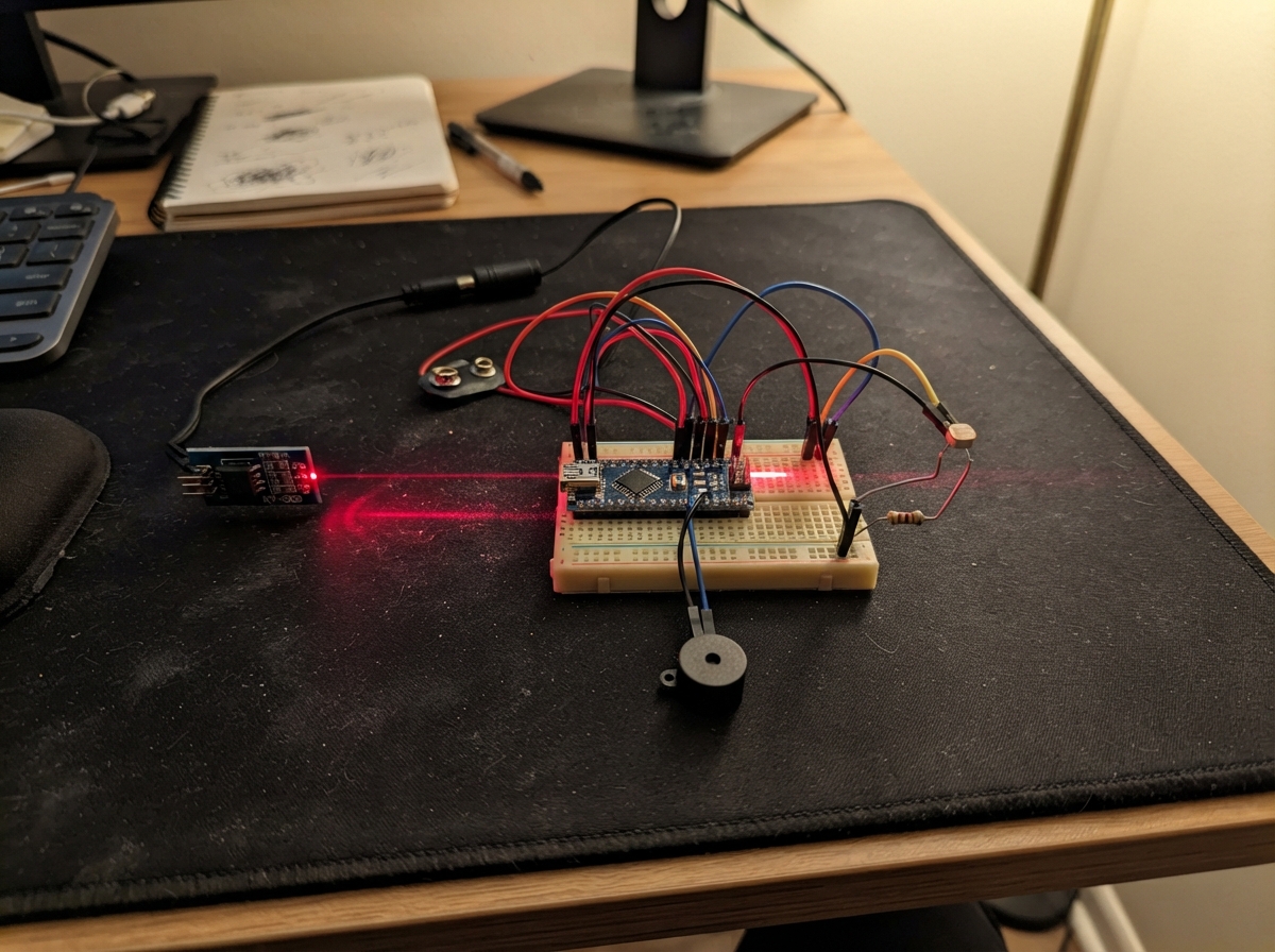
Build a playable laser harp that produces musical notes when laser beams are interrupted. This project uses five laser modules arranged in a harp-like configuration, with photoresistors detecting when each beam is blocked. An Arduino Uno processes the sensor readings and triggers a piezo buzzer to play the corresponding note from a five-note musical scale (do, re, mi, fa, sol).
This guide provides a complete wiring diagram, parts list, and step-by-step assembly instructions for mounting the laser harp frame and aligning the five sensing points. The included firmware handles beam calibration on startup, debounces rapid retriggering, and maps beam interruptions to specific frequencies. Builders will have everything needed to assemble a working musical instrument.
Wiring diagram

Gather all the parts
Assemble it in 4 steps
1. Monte o aro com segurança
Faça uma base circular firme de madeira, papelão grosso ou uma peça impressa. Prenda os cinco lasers na borda e coloque a LDR correspondente exatamente do outro lado, apontada para o seu laser: Dó, Ré, Mi, Fá e Sol. Cubra cada LDR com um pequeno tubo preto, deixando somente a ponta voltada para o laser correspondente.
- Teste e alinhe um par laser–LDR de cada vez antes de instalar o próximo.
- Mantenha os cinco feixes apontados para o centro do aro.
- Mantenha os feixes abaixo da altura dos olhos e terminando dentro do tubo do sensor; nunca aponte lasers para pessoas, animais, espelhos ou janelas.
- Use apenas módulos laser de baixa potência Classe 1 ou Classe 2.
2. Monte os cinco pontos de leitura
Para cada nota, coloque uma perna da LDR e uma ponta do resistor de 10 kΩ no mesmo ponto da protoboard. Ligue a outra perna da LDR ao 5V (alimentação) e a outra ponta do resistor ao GND (terra). Leve cada ponto compartilhado ao Arduino Uno: Dó → A0 (sinal), Ré → A1 (sinal), Mi → A2 (sinal), Fá → A3 (sinal) e Sol → A4 (sinal).
- Os resistores não têm lado certo.
- Em cada nota: uma perna da LDR → 5V (alimentação), uma ponta do resistor → GND (terra), e o ponto unido entre LDR e resistor → A0 a A4 (sinal).
- Não ligue o ponto compartilhado entre LDR e resistor diretamente ao 5V ou ao GND: é esse ponto que o Arduino precisa ler.
3. Ligue os lasers e o piezo
Em cada KY-008, ligue VCC → 5V (alimentação), GND → GND (terra) e S → 5V (mantém o laser ligado). Ligue uma perna do piezo → D8 (som) e a outra perna → GND (terra). Todos os fios GND precisam estar unidos.
- Se o piezo tiver um símbolo +, ligue essa perna ao D8.
- Organize os fios de 5V e GND em trilhos separados da protoboard.
- Confira as marcações VCC e GND de cada laser antes de energizar: alimentação invertida pode danificar o módulo.
4. Calibre quando ligar
Conecte o Arduino Uno ao USB. Nos primeiros dois segundos, deixe os cinco lasers alinhados e sem nenhuma mão bloqueando os feixes; depois interrompa um feixe de cada vez para tocar Dó, Ré, Mi, Fá ou Sol.
- Se uma nota tocar sem a sua mão, direcione melhor o laser para o centro da LDR e escureça o tubo preto.
- Se uma nota não tocar, confira se o laser correspondente chega à LDR correta.
- Não olhe diretamente para um feixe durante o alinhamento.
Review all connections
1. Connections between "laser_do" and "Arduino"
2. Connections between "laser_re" and "Arduino"
3. Connections between "laser_mi" and "Arduino"
4. Connections between "laser_fa" and "Arduino"
5. Connections between "laser_sol" and "Arduino"
6. Connections between "ldr_do" and "Arduino"
7. Connections between "resistor_do" and "Arduino"
8. Connections between "ldr_re" and "Arduino"
9. Connections between "resistor_re" and "Arduino"
10. Connections between "ldr_mi" and "Arduino"
11. Connections between "resistor_mi" and "Arduino"
12. Connections between "ldr_fa" and "Arduino"
13. Connections between "resistor_fa" and "Arduino"
14. Connections between "ldr_sol" and "Arduino"
15. Connections between "resistor_sol" and "Arduino"
16. Connections between "piezo" and "Arduino"
Deploy the firmware
#include <Arduino.h>

int readAverage(uint8_t pin);
void calibrateBeams();

constexpr uint8_t SENSOR_DO_PIN = A0;
constexpr uint8_t SENSOR_RE_PIN = A1;
constexpr uint8_t SENSOR_MI_PIN = A2;
constexpr uint8_t SENSOR_FA_PIN = A3;
constexpr uint8_t SENSOR_SOL_PIN = A4;
constexpr uint8_t PIEZO_PIN = 8;

constexpr uint8_t NOTE_COUNT = 5;
const uint8_t sensorPins[NOTE_COUNT] = {
  SENSOR_DO_PIN, SENSOR_RE_PIN, SENSOR_MI_PIN, SENSOR_FA_PIN, SENSOR_SOL_PIN
};
const uint16_t noteHz[NOTE_COUNT] = {262, 294, 330, 349, 392};

int brightLevel[NOTE_COUNT] = {};
int blockedThreshold[NOTE_COUNT] = {};
bool beamBlocked[NOTE_COUNT] = {};
unsigned long lastTriggerMs[NOTE_COUNT] = {};

constexpr unsigned long CALIBRATION_MS = 2000;
constexpr unsigned long RETRIGGER_MS = 180;
constexpr unsigned long NOTE_MS = 220;

int readAverage(uint8_t pin) {
  long total = 0;
  for (uint8_t sample = 0; sample < 8; sample++) {
    total += analogRead(pin);
    delay(2);
  }
  return total / 8;
}

void calibrateBeams() {
  long totals[NOTE_COUNT] = {};
  uint16_t samples = 0;
  const unsigned long started = millis();

  while (millis() - started < CALIBRATION_MS) {
    for (uint8_t i = 0; i < NOTE_COUNT; i++) {
      totals[i] += analogRead(sensorPins[i]);
    }
    samples++;
    delay(5);
  }

  for (uint8_t i = 0; i < NOTE_COUNT; i++) {
    brightLevel[i] = totals[i] / samples;
    blockedThreshold[i] = (brightLevel[i] * 70L) / 100L;
  }
}

void setup() {
  Serial.begin(115200);
  pinMode(PIEZO_PIN, OUTPUT);
  noTone(PIEZO_PIN);

  Serial.println(F("Harpa laser: deixe os cinco feixes livres por dois segundos."));
  calibrateBeams();
  Serial.println(F("Pronta: bloqueie um feixe para tocar Do, Re, Mi, Fa ou Sol."));
}

void loop() {
  const unsigned long now = millis();

  for (uint8_t i = 0; i < NOTE_COUNT; i++) {
    const bool nowBlocked = readAverage(sensorPins[i]) < blockedThreshold[i];

    if (nowBlocked && !beamBlocked[i] && now - lastTriggerMs[i] >= RETRIGGER_MS) {
      tone(PIEZO_PIN, noteHz[i], NOTE_MS);
      lastTriggerMs[i] = now;
    }

    beamBlocked[i] = nowBlocked;
  }
}
Remix this project
Make it yours in one click
Open a full copy of this project in your own Schematik workspace — diagram, code, parts, and assembly steps included. Swap the sensor, add features, or redesign the whole thing with AI. The author's original stays untouched.
Related projects
Necesito Hacer Un Circuito De Un Oxiometro Con
Arduino · September 25, 2026MARIA PAULA LAMBOGLIA VARGAS
Três Sensores de Luz
Arduino · September 25, 2026arthur.brazil
Make Arduino Rotating Clock Using Led Line
Arduino · September 23, 2026Pruthivi Sampath