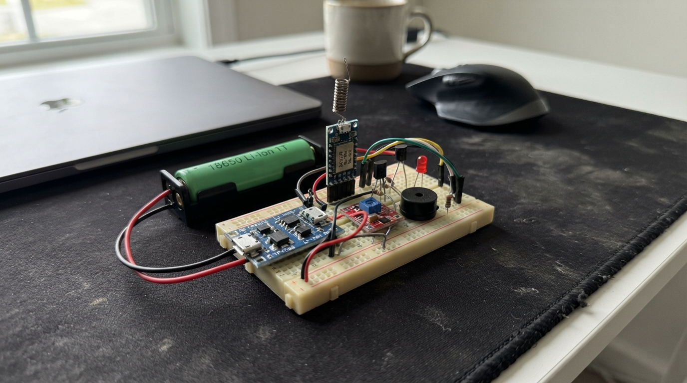
This project builds a remote battery monitoring system using LoRa wireless communication to track 18650 Li-ion cell voltage and trigger alarms when battery levels drop too low. The ESP32 microcontroller reads battery voltage through a resistor divider, communicates status via the SX1278 LoRa module, and activates a buzzer alarm through a transistor switch when thresholds are breached. The TP4056 charger module with integrated protection manages safe charging of the Li-ion cell, while a boost converter provides stable 5V power for the buzzer and logic circuits.
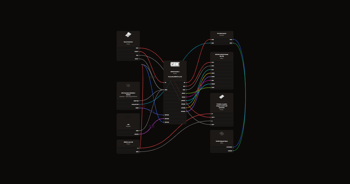
This guide provides a complete parts list, wiring diagram showing all connections from the ESP32 to the LoRa module, charger, buzzer, and battery measurement circuit, plus step-by-step assembly instructions. Firmware code is included to configure the LoRa radio, monitor battery voltage, send wireless alerts, and control the alarm buzzer based on user-defined voltage thresholds.
Wiring diagram
Gather all the parts
Assemble it in 6 steps
1. Place the board and prepare rails
Place the 30-pin ESP32 on the left, leaving free columns on the right. Top + is 5 V, bottom + is 3.3 V. Join top - to bottom - for common ground. ESP32 VIN goes to top +, GND to top -, and 3V3 to bottom +. Never join the two positive rails. Check for split power rails and bridge matching halves if needed.
- Some ESP32 boards leave no usable holes beside their pins on a single breadboard; use two breadboards side by side if necessary.
2. Connect battery power
Battery positive to TP4056 B+, negative to B-. OUT+ to boost IN+ and OUT- to boost IN-. With the ESP32 disconnected, measure and adjust boost OUT to 5.0 V. Then connect OUT+ to top + and OUT- to top -. Use the protected TP4056 version with B+/B- and OUT+/OUT- terminals.
- Use an insulated cell holder; do not solder directly to the cell. Reversed polarity or a short can cause fire.
- Disconnect the boost 5 V wire from the breadboard before connecting ESP32 USB; do not connect both supplies together.
- TP4056 has no load sharing: disconnect the load while charging, and set charge current within the cell rating.
- The battery-monitor lower resistor connects to OUT- common ground, not directly to B-; this preserves the protection circuit.
3. Wire the LoRa module
VCC to bottom + (3.3 V), GND to common ground. SCK to GPIO18 (clock), MISO to GPIO19 (radio data out), MOSI to GPIO23 (radio data in), NSS to GPIO5 (select), RST to GPIO14 (reset), DIO0 to GPIO4 (interrupt).
- Never power the radio from 5 V. Attach the matching antenna before any future radio transmission.
- GPIO5 is a boot-strapping pin, also the listed default SPI select. Do not add circuitry that forces it low at startup.
4. Wire the buzzer switch
GPIO25 to the 1 kohm resistor; its other lead and transistor base share row 30 a-e. Emitter to ground. Collector and buzzer negative share row 32 a-e. Buzzer positive to top +. Put the diode across the buzzer: banded end to positive, other end to row 32.
- Check the actual transistor datasheet for base, collector and emitter positions; 2N2222 and BC547 lead orders differ. Do not guess from the flat face.
5. Wire the indicator
GPIO26 to the 220 ohm resistor. Its other lead and LED anode share row 50 a-e. LED cathode (short leg, flat-edge side) to ground.
6. Wire battery measurement
Battery positive and R1 first lead share row 40 a-e. R1 second lead, R2 first lead and GPIO35 share row 42 a-e. R2 second lead to common ground. Both resistors are 100 kohm; the divider limits a fully charged 4.2 V cell to 2.1 V at GPIO35.
- Each numbered a-e strip is one connection; f-j is a separate strip across the centre gap. Keep row 30, 32, 40, 42 and 50 separate.
Review all connections
1. Connections between "battery" and "ESP32"
2. Connections between "charger" and "ESP32"
3. Connections between "boost" and "ESP32"
4. Connections between "radio" and "ESP32"
5. Connections between "baseR" and "ESP32"
6. Connections between "transistor" and "ESP32"
7. Connections between "buzzer" and "ESP32"
8. Connections between "diode" and "ESP32"
9. Connections between "ledR" and "ESP32"
10. Connections between "indicator" and "ESP32"
11. Connections between "r1" and "ESP32"
12. Connections between "r2" and "ESP32"
Deploy the firmware
#include <Arduino.h>
// Wiring-only placeholder: no radio, alarm or measurement behaviour.
void setup() {
  digitalWrite(25, LOW); pinMode(25, OUTPUT);
  digitalWrite(26, LOW); pinMode(26, OUTPUT);
}
void loop() { delay(1000); }
Remix this project
Make it yours in one click
Open a full copy of this project in your own Schematik workspace, diagram, code, parts, and assembly steps included. Swap the sensor, add features, or redesign the whole thing with AI. The author's original stays untouched.