Community project
Make The Data From Icm-29048 Bord Available Via
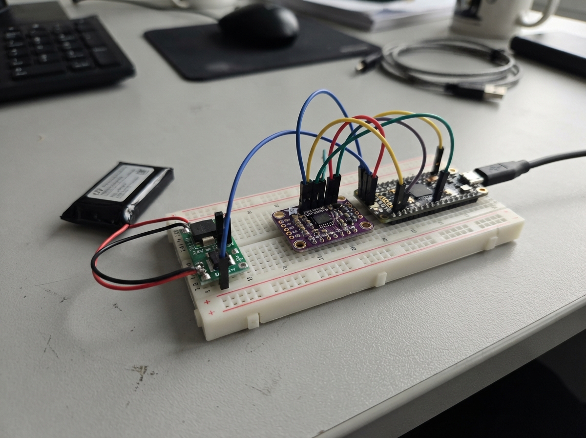
This project makes a 9-axis inertial measurement unit (IMU) based on the Adafruit ICM-20948 sensor available over WiFi using an ESP32 microcontroller. The ICM-20948 provides accelerometer, gyroscope, and magnetometer data that the ESP32 reads via I2C, then broadcasts as NMEA sentences over UDP to connected devices. A 12V rechargeable battery powers the system through a buck converter that steps the voltage down to 5V for the ESP32 and sensor.
This guide provides a complete parts list, wiring diagram showing all I2C and power connections, step-by-step assembly instructions, and Arduino firmware with built-in calibration routines for accurate sensor readings. The firmware includes WiFi AP mode for easy network access, UDP broadcasting for real-time data streaming, and persistent storage of calibration values so the sensor remains accurate across power cycles.
Wiring diagram

Gather all the parts
Assemble it in 7 steps
1. Leave the battery disconnected
Place the ESP32, ICM-20948, LM2596 step-down module, and 12 V battery where you can see their printed labels. Do not connect the battery while fitting wires or adjusting the converter.
- Use a small screwdriver only for the converter adjustment screw.
- Do not connect the 12 V battery directly to any ESP32 pin or to the sensor — 12 V can permanently damage both parts.
2. Set the converter to 5 volts
Connect the 12 V battery positive terminal to LM2596 VIN+ (power) and battery negative terminal to LM2596 VIN- (ground). Use a multimeter across VOUT+ and VOUT-, then turn the small adjustment screw until the meter reads 5.0 V before connecting the ESP32.
- Turn the screw a little at a time and recheck the meter after each adjustment.
- Do not skip the meter check — some modules are adjusted above 5 V when delivered, and excess voltage can damage the ESP32.
3. Power the ESP32 from the converter
With the battery disconnected again, connect LM2596 VOUT+ to the ESP32 5V or VIN pin (power). Connect LM2596 VOUT- to an ESP32 GND pin (ground). Reconnect the battery only after checking these two wires.
- The converter ground and ESP32 ground must be connected or the sensor signals cannot work correctly.
- Keep the ESP32 USB cable unplugged while the 12 V battery powers its 5V or VIN pin unless your board specifically provides safe power-source isolation.
4. Connect the motion sensor power
Connect ICM-20948 VIN to the ESP32 3V3 pin (power). Connect ICM-20948 GND to an ESP32 GND pin (ground). The ESP32's 3V3 pin safely powers the sensor from the regulated supply.
- Follow the VIN and GND labels printed beside the sensor pins.
- Make sure VIN and GND are not swapped — swapped power can damage the sensor.
5. Connect the motion signal wires
Connect ICM-20948 SDA to ESP32 GPIO21 (data). Connect ICM-20948 SCL to ESP32 GPIO22 (clock). Leave SDO/ADR, CS, and INT unconnected for this I2C build.
- SDA and SCL are different wires; if they are swapped, the ESP32 cannot find the sensor.
- Do not connect the sensor signal pins to 5 V.
6. Mount the sensor away from magnetic parts
Fasten the ICM-20948 firmly in its final direction, at least 15 cm away from the LM2596 converter, 12 V battery, thick battery wires, steel screws, and speakers. Keep its printed top surface facing upward when the unit is sitting normally. This gives the compass a cleaner reading and makes still calibration accurate.
- Use nylon screws or non-metallic tape near the sensor when possible.
- Do not move the sensor after calibration; if you must move it, calibrate again.
- The converter and battery wires can distort compass readings even though the sensor is electrically wired correctly.
7. Power and deploy the finished unit
Check the LM2596 output is still 5.0 V, then connect the 12 V battery. The ESP32 creates the IMU-NMEA Wi-Fi network and sends UDP data on port 10110. Plug in USB only when you want Schematik to deploy firmware, with the battery disconnected first.
- After deployment, join Wi-Fi network IMU-NMEA using password imu-nmea-2026 and listen for UDP packets on port 10110.
- If the ESP32 gets hot or its power light behaves unusually, disconnect the battery immediately and recheck the converter output and wire polarity.
Review all connections
1. Connections between "icm20948_1" and "ESP32"
2. Connections between "battery_12v_1" and "ESP32"
3. Connections between "buck_5v_1" and "ESP32"
Deploy the firmware
#include <Arduino.h>
#include <Wire.h>
#include <WiFi.h>
#include <WiFiUdp.h>
#include <Preferences.h>


// Forward declarations
bool writeRegister(uint8_t address, uint8_t reg, uint8_t value);
bool readRegisters(uint8_t address, uint8_t reg, uint8_t *data, size_t length);
bool selectIcmBank(uint8_t bank);
int16_t bigEndian16(const uint8_t *data);
int16_t littleEndian16(const uint8_t *data);
bool beginImu();
uint8_t nmeaChecksum(const char *text);
void sendImuSentence();
bool readRawImu(int16_t &ax, int16_t &ay, int16_t &az, int16_t &gx, int16_t &gy, int16_t &gz, int16_t &mx, int16_t &my, int16_t &mz);
void loadCalibration();
void saveCalibration();
void calibrateStill();
void startMagCalibration();
void finishMagCalibration();
void handleSerialCommands();

constexpr int I2C_SDA_PIN = 21;
constexpr int I2C_SCL_PIN = 22;
constexpr uint8_t ICM_ADDRESS = 0x69;
constexpr uint8_t MAG_ADDRESS = 0x0C;
constexpr uint16_t UDP_PORT = 10110;
constexpr uint32_t SEND_INTERVAL_MS = 100;

const char *AP_NAME = "imu-nmea";
const char *AP_PASSWORD = "mve-imu-2026";
const IPAddress UDP_BROADCAST(10, 42, 0, 4);

WiFiUDP udp;
Preferences preferences;
uint32_t lastSendMs = 0;

// These corrections are stored in the ESP32, so they remain after battery power is removed.
float accelBias[3] = {0.0f, 0.0f, 0.0f};
float gyroBias[3] = {0.0f, 0.0f, 0.0f};
float magOffset[3] = {0.0f, 0.0f, 0.0f};
float magScale[3] = {1.0f, 1.0f, 1.0f};
bool magCalibrating = false;
int16_t magMin[3] = {32767, 32767, 32767};
int16_t magMax[3] = {-32768, -32768, -32768};

bool writeRegister(uint8_t address, uint8_t reg, uint8_t value) {
  Wire.beginTransmission(address);
  Wire.write(reg);
  Wire.write(value);
  return Wire.endTransmission() == 0;
}

bool readRegisters(uint8_t address, uint8_t reg, uint8_t *data, size_t length) {
  Wire.beginTransmission(address);
  Wire.write(reg);
  if (Wire.endTransmission(false) != 0) return false;
  const size_t received = Wire.requestFrom(static_cast<int>(address), static_cast<int>(length));
  if (received != length) return false;
  for (size_t i = 0; i < length; ++i) data[i] = Wire.read();
  return true;
}

bool selectIcmBank(uint8_t bank) {
  return writeRegister(ICM_ADDRESS, 0x7F, static_cast<uint8_t>(bank << 4));
}

int16_t bigEndian16(const uint8_t *data) {
  return static_cast<int16_t>((static_cast<uint16_t>(data[0]) << 8) | data[1]);
}

int16_t littleEndian16(const uint8_t *data) {
  return static_cast<int16_t>((static_cast<uint16_t>(data[1]) << 8) | data[0]);
}

bool beginImu() {
  uint8_t whoAmI = 0;
  if (!selectIcmBank(0) || !readRegisters(ICM_ADDRESS, 0x00, &whoAmI, 1) || whoAmI != 0xEA) return false;

  // Wake the ICM-20948, use its internal clock, and expose the onboard magnetometer on I2C.
  if (!writeRegister(ICM_ADDRESS, 0x06, 0x01)) return false;
  delay(50);
  if (!writeRegister(ICM_ADDRESS, 0x0F, 0x02)) return false;
  if (!selectIcmBank(2)) return false;
  // ±4 g accelerometer (8192 counts/g) and ±500 degrees/s gyroscope (65.5 counts/degree/s).
  if (!writeRegister(ICM_ADDRESS, 0x14, 0x01) || !writeRegister(ICM_ADDRESS, 0x01, 0x02)) return false;
  if (!selectIcmBank(0)) return false;

  // Reset and start the AK09916 magnetometer in continuous 100 Hz mode.
  if (!writeRegister(MAG_ADDRESS, 0x32, 0x01)) return false;
  delay(10);
  if (!writeRegister(MAG_ADDRESS, 0x31, 0x08)) return false;
  return true;
}

bool readRawImu(int16_t &ax, int16_t &ay, int16_t &az, int16_t &gx, int16_t &gy, int16_t &gz, int16_t &mx, int16_t &my, int16_t &mz) {
  uint8_t imuData[12];
  uint8_t magData[8];
  if (!selectIcmBank(0) || !readRegisters(ICM_ADDRESS, 0x2D, imuData, sizeof(imuData))) return false;
  if (!readRegisters(MAG_ADDRESS, 0x10, magData, sizeof(magData)) || !(magData[0] & 0x01) || (magData[7] & 0x08)) return false;
  ax = bigEndian16(&imuData[0]); ay = bigEndian16(&imuData[2]); az = bigEndian16(&imuData[4]);
  gx = bigEndian16(&imuData[6]); gy = bigEndian16(&imuData[8]); gz = bigEndian16(&imuData[10]);
  mx = littleEndian16(&magData[1]); my = littleEndian16(&magData[3]); mz = littleEndian16(&magData[5]);
  return true;
}

void loadCalibration() {
  preferences.begin("imu-cal", true);
  accelBias[0] = preferences.getFloat("abx", 0); accelBias[1] = preferences.getFloat("aby", 0); accelBias[2] = preferences.getFloat("abz", 0);
  gyroBias[0] = preferences.getFloat("gbx", 0); gyroBias[1] = preferences.getFloat("gby", 0); gyroBias[2] = preferences.getFloat("gbz", 0);
  magOffset[0] = preferences.getFloat("mox", 0); magOffset[1] = preferences.getFloat("moy", 0); magOffset[2] = preferences.getFloat("moz", 0);
  magScale[0] = preferences.getFloat("msx", 1); magScale[1] = preferences.getFloat("msy", 1); magScale[2] = preferences.getFloat("msz", 1);
  preferences.end();
}

void saveCalibration() {
  preferences.begin("imu-cal", false);
  preferences.putFloat("abx", accelBias[0]); preferences.putFloat("aby", accelBias[1]); preferences.putFloat("abz", accelBias[2]);
  preferences.putFloat("gbx", gyroBias[0]); preferences.putFloat("gby", gyroBias[1]); preferences.putFloat("gbz", gyroBias[2]);
  preferences.putFloat("mox", magOffset[0]); preferences.putFloat("moy", magOffset[1]); preferences.putFloat("moz", magOffset[2]);
  preferences.putFloat("msx", magScale[0]); preferences.putFloat("msy", magScale[1]); preferences.putFloat("msz", magScale[2]);
  preferences.end();
}

void calibrateStill() {
  Serial.println("Keep the unit flat and completely still for 5 seconds.");
  delay(1000);
  int64_t sums[6] = {0, 0, 0, 0, 0, 0};
  int samples = 0;
  const uint32_t started = millis();
  while (millis() - started < 5000) {
    int16_t ax, ay, az, gx, gy, gz, mx, my, mz;
    if (readRawImu(ax, ay, az, gx, gy, gz, mx, my, mz)) {
      sums[0] += ax; sums[1] += ay; sums[2] += az; sums[3] += gx; sums[4] += gy; sums[5] += gz;
      ++samples;
    }
    delay(10);
  }
  if (samples == 0) { Serial.println("Calibration failed: no IMU samples."); return; }
  accelBias[0] = sums[0] / static_cast<float>(samples);
  accelBias[1] = sums[1] / static_cast<float>(samples);
  accelBias[2] = sums[2] / static_cast<float>(samples) - 8192.0f; // Flat board, label facing upward.
  gyroBias[0] = sums[3] / static_cast<float>(samples); gyroBias[1] = sums[4] / static_cast<float>(samples); gyroBias[2] = sums[5] / static_cast<float>(samples);
  saveCalibration();
  Serial.println("Still calibration saved.");
}

void startMagCalibration() {
  magCalibrating = true;
  for (int i = 0; i < 3; ++i) { magMin[i] = 32767; magMax[i] = -32768; }
  Serial.println("Compass calibration started. Rotate the whole unit slowly through every direction, then send S.");
}

void finishMagCalibration() {
  if (!magCalibrating) return;
  const float radii[3] = {(magMax[0] - magMin[0]) * 0.5f, (magMax[1] - magMin[1]) * 0.5f, (magMax[2] - magMin[2]) * 0.5f};
  if (radii[0] < 10 || radii[1] < 10 || radii[2] < 10) { Serial.println("Compass calibration failed: rotate through all directions and try again."); return; }
  const float averageRadius = (radii[0] + radii[1] + radii[2]) / 3.0f;
  for (int i = 0; i < 3; ++i) { magOffset[i] = (magMax[i] + magMin[i]) * 0.5f; magScale[i] = averageRadius / radii[i]; }
  magCalibrating = false;
  saveCalibration();
  Serial.println("Compass calibration saved.");
}

void handleSerialCommands() {
  while (Serial.available()) {
    const char command = toupper(Serial.read());
    if (command == 'C') calibrateStill();
    else if (command == 'M') startMagCalibration();
    else if (command == 'S') finishMagCalibration();
    else if (command == 'H' || command == '?') Serial.println("Commands: C=still calibration, M=start compass calibration, S=save compass calibration.");
  }
}

uint8_t nmeaChecksum(const char *text) {
  uint8_t checksum = 0;
  while (*text != '\0') checksum ^= static_cast<uint8_t>(*text++);
  return checksum;
}

void sendImuSentence() {
  int16_t rawAx, rawAy, rawAz, rawGx, rawGy, rawGz, rawMx, rawMy, rawMz;
  if (!readRawImu(rawAx, rawAy, rawAz, rawGx, rawGy, rawGz, rawMx, rawMy, rawMz)) return;
  if (magCalibrating) {
    const int16_t rawMag[3] = {rawMx, rawMy, rawMz};
    for (int i = 0; i < 3; ++i) { if (rawMag[i] < magMin[i]) magMin[i] = rawMag[i]; if (rawMag[i] > magMax[i]) magMax[i] = rawMag[i]; }
  }

  const float accelScale = 9.80665f / 8192.0f;
  const float gyroScale = (PI / 180.0f) / 65.5f;
  const float magnetometerScale = 0.15f;
  const float ax = (rawAx - accelBias[0]) * accelScale;
  const float ay = (rawAy - accelBias[1]) * accelScale;
  const float az = (rawAz - accelBias[2]) * accelScale;
  const float gx = (rawGx - gyroBias[0]) * gyroScale;
  const float gy = (rawGy - gyroBias[1]) * gyroScale;
  const float gz = (rawGz - gyroBias[2]) * gyroScale;
  const float mx = (rawMx - magOffset[0]) * magScale[0] * magnetometerScale;
  const float my = (rawMy - magOffset[1]) * magScale[1] * magnetometerScale;
  const float mz = (rawMz - magOffset[2]) * magScale[2] * magnetometerScale;

  char payload[180];
  snprintf(payload, sizeof(payload), "PIMU,%.2f,%.3f,%.3f,%.3f,%.5f,%.5f,%.5f,%.2f,%.2f,%.2f",
           millis() / 1000.0f, ax, ay, az, gx, gy, gz, mx, my, mz);
  char sentence[190];
  snprintf(sentence, sizeof(sentence), "$%s*%02X\r\n", payload, nmeaChecksum(payload));
  udp.beginPacket(UDP_BROADCAST, UDP_PORT);
  udp.write(reinterpret_cast<const uint8_t *>(sentence), strlen(sentence));
  udp.endPacket();
  Serial.print(sentence);
}

void setup() {
  Serial.begin(115200);
  Wire.begin(I2C_SDA_PIN, I2C_SCL_PIN);
  if (!beginImu()) {
    Serial.println("ICM-20948 was not found. Check VIN, GND, SDA, and SCL.");
    while (true) delay(1000);
  }
  loadCalibration();
  Serial.println("Calibration commands: C=still, M=start compass, S=save compass, H=help.");
  WiFi.mode(WIFI_AP);
  WiFi.softAP(AP_NAME, AP_PASSWORD);
  udp.begin(UDP_PORT);
  Serial.println("ICM-20948 UDP NMEA transmitter ready.");
}

void loop() {
  handleSerialCommands();
  const uint32_t now = millis();
  if (now - lastSendMs >= SEND_INTERVAL_MS) {
    lastSendMs = now;
    sendImuSentence();
  }
}
Remix this project
Make it yours in one click
Open a full copy of this project in your own Schematik workspace — diagram, code, parts, and assembly steps included. Swap the sensor, add features, or redesign the whole thing with AI. The author's original stays untouched.