Community project
MAX7219 Scrolling Display
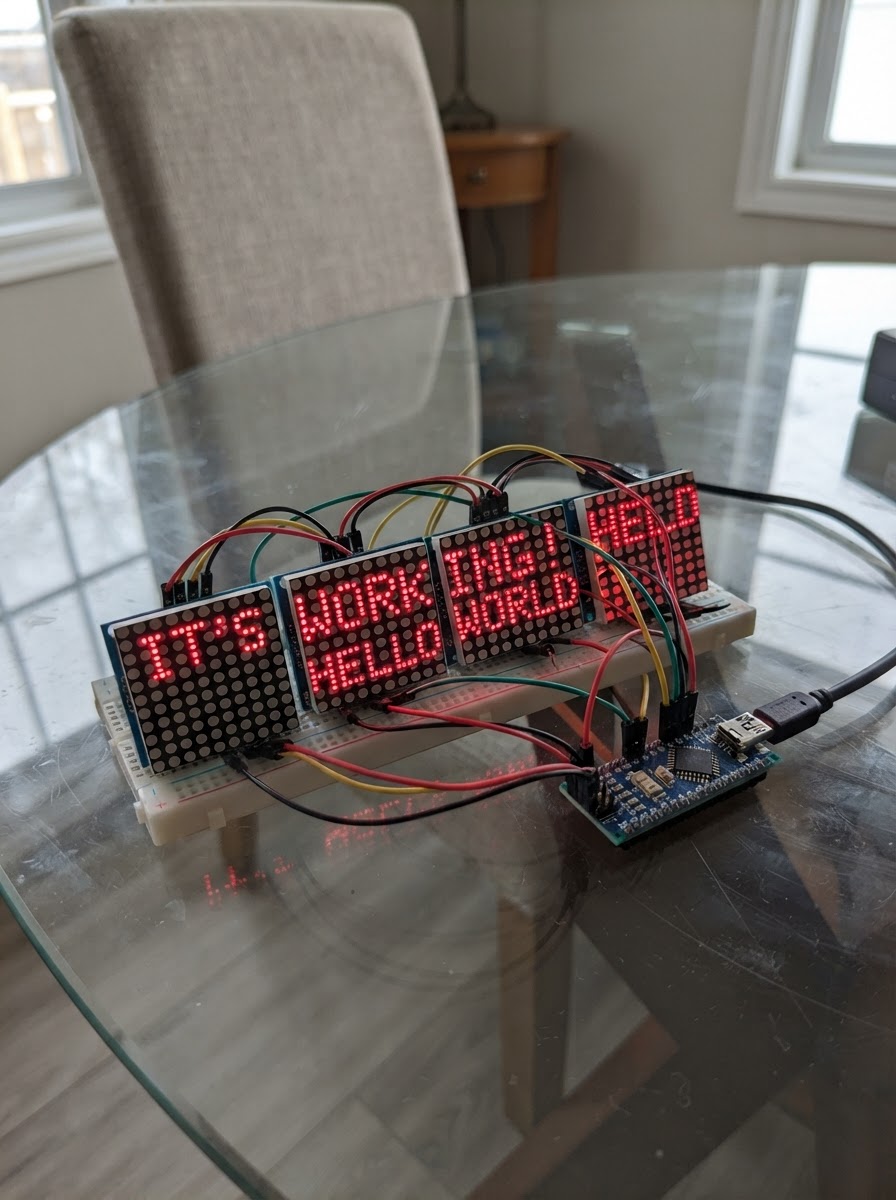
This guide builds a scrolling text display using five chained MAX7219 8x8 LED matrix modules controlled by an Arduino Uno. The result is a 40×8 pixel display capable of smooth horizontal text animation, perfect for signs, notifications, or information panels.
The guide includes a complete wiring diagram showing how to connect the DIN, CLK, and CS pins from the Arduino to the matrix chain, a full parts list, and ready-to-use firmware with a built-in font renderer. Assembly takes about 30 minutes and requires only basic soldering; the included code handles all the timing and pixel-by-pixel rendering needed to make text scroll smoothly across the display.
Wiring diagram

Gather all the parts
Assemble it in 4 steps
1. Monte a faixa de cinco matrizes
Coloque os cinco módulos MAX7219 lado a lado, formando uma faixa de 40 × 8 LEDs. Depois de encadear as placas, vire a faixa inteira 180° antes de fixá-la. Não gire uma placa isoladamente.
- Todos os módulos devem manter a mesma orientação relativa.
- O firmware compensa a montagem do conjunto girado.
2. Encadeie os dados entre os módulos
Ligue DOUT do módulo 1 ao DIN do módulo 2, DOUT do 2 ao DIN do 3, DOUT do 3 ao DIN do 4 e DOUT do 4 ao DIN do 5. Somente o DIN do módulo 1 recebe dados do Arduino.
- Distribua CLK, CS/LOAD, 5 V e GND em paralelo para todos os módulos.
- Não conecte todos os pinos DIN ao D11: isso repete a imagem, em vez de formar uma faixa única.
3. Ligue o painel ao Arduino Uno
Conecte D11 ao DIN do primeiro módulo, D13 ao CLK de todos os módulos, D10 ao CS/LOAD de todos, 5 V ao VCC e GND ao GND.
- Mantenha os fios de alimentação curtos e una todos os GND.
- O ESP-01 não é usado neste firmware; mantenha-o desconectado durante este teste.
4. Teste o texto rolante
Alimente o Uno pelo USB e use o botão Deploy. O painel exibirá continuamente a mensagem "OLA! SCROLLER PRONTO" rolando pela faixa.
- O brilho inicial está no nível 3 e pode ser ajustado depois no código.
- Se houver pixels instáveis, queda de brilho ou reinicializações, use uma fonte externa regulada de 5 V para as matrizes e conecte o GND dela ao GND do Uno.
Review all connections
1. Connections between "matrix_chain" and "Arduino"
Deploy the firmware
#include <Arduino.h>
#include <MD_MAX72xx.h>
#include <SPI.h>

// Cinco matrizes MAX7219 genericas, em uma faixa de 40 x 8 pixels.

// Forward declarations
int glyphIndex(char c);
bool messagePixel(int logicalX, int y);
void drawFrame(int offset);

const uint8_t DIN_PIN = 11;
const uint8_t CLK_PIN = 13;
const uint8_t CS_PIN = 10;
const uint8_t MODULE_COUNT = 5;
const uint8_t PANEL_WIDTH = MODULE_COUNT * 8;
const uint16_t SCROLL_SPEED_MS = 30;

MD_MAX72XX matrix(MD_MAX72XX::GENERIC_HW, DIN_PIN, CLK_PIN, CS_PIN, MODULE_COUNT);
const char MESSAGE[] = "  OLA! SCROLLER PRONTO  ";

// Cada glifo possui 5 colunas; o bit 0 de cada coluna e a linha superior.
const uint8_t FONT[][5] = {
  {0x00,0x00,0x00,0x00,0x00},
  {0x00,0x00,0x5f,0x00,0x00},
  {0x7e,0x09,0x09,0x09,0x7e},
  {0x7f,0x49,0x49,0x49,0x36},
  {0x3e,0x41,0x41,0x41,0x22},
  {0x7f,0x41,0x41,0x22,0x1c},
  {0x7f,0x49,0x49,0x49,0x41},
  {0x7f,0x09,0x09,0x09,0x01},
  {0x3e,0x41,0x49,0x49,0x7a},
  {0x7f,0x08,0x08,0x08,0x7f},
  {0x00,0x41,0x7f,0x41,0x00},
  {0x20,0x40,0x41,0x3f,0x01},
  {0x7f,0x08,0x14,0x22,0x41},
  {0x7f,0x40,0x40,0x40,0x40},
  {0x7f,0x02,0x0c,0x02,0x7f},
  {0x7f,0x04,0x08,0x10,0x7f},
  {0x3e,0x41,0x41,0x41,0x3e},
  {0x7f,0x09,0x09,0x09,0x06},
  {0x3e,0x41,0x51,0x21,0x5e},
  {0x7f,0x09,0x19,0x29,0x46},
  {0x46,0x49,0x49,0x49,0x31},
  {0x01,0x01,0x7f,0x01,0x01},
  {0x3f,0x40,0x40,0x40,0x3f},
  {0x1f,0x20,0x40,0x20,0x1f},
  {0x7f,0x20,0x18,0x20,0x7f},
  {0x63,0x14,0x08,0x14,0x63},
  {0x07,0x08,0x70,0x08,0x07},
  {0x61,0x51,0x49,0x45,0x43}
};

int glyphIndex(char c) {
  if (c == ' ') return 0;
  if (c == '!') return 1;
  if (c >= 'A' && c <= 'Z') return c - 'A' + 2;
  return 0;
}

bool messagePixel(int logicalX, int y) {
  if (logicalX < 0) return false;
  int character = logicalX / 6;
  int column = logicalX % 6;
  if (character >= (int)strlen(MESSAGE) || column == 5) return false;
  return FONT[glyphIndex(MESSAGE[character])][column] & (1 << y);
}

void drawFrame(int offset) {
  // Uma escrita por coluna evita apagar o painel e reduz o flicker.
  for (int x = 0; x < PANEL_WIDTH; x++) {
    uint8_t columnData = 0;
    for (int y = 0; y < 8; y++) {
      if (messagePixel(x + offset, y)) {
        // Compensa a montagem fisica do conjunto girado 180 graus.
        columnData |= (1 << (7 - y));
      }
    }
    matrix.setColumn(x, columnData);
  }
}

void setup() {
  matrix.begin();
  matrix.control(MD_MAX72XX::INTENSITY, 3);
}

void loop() {
  static int offset = 0;
  static unsigned long lastFrame = 0;
  const int messageWidth = strlen(MESSAGE) * 6;
  unsigned long now = millis();

  if (now - lastFrame >= SCROLL_SPEED_MS) {
    lastFrame = now;
    drawFrame(offset);
    offset++;
    if (offset >= messageWidth) offset = -PANEL_WIDTH;
  }
}
Remix this project
Make it yours in one click
Open a full copy of this project in your own Schematik workspace — diagram, code, parts, and assembly steps included. Swap the sensor, add features, or redesign the whole thing with AI. The author's original stays untouched.
Related projects
Necesito Hacer Un Circuito De Un Oxiometro Con
Arduino · September 25, 2026MARIA PAULA LAMBOGLIA VARGAS
Laser Harp Instrument
Arduino · September 25, 2026juliasualoka2
Três Sensores de Luz
Arduino · September 25, 2026arthur.brazil