Community project
Mecanum Balancing Inventory Robot
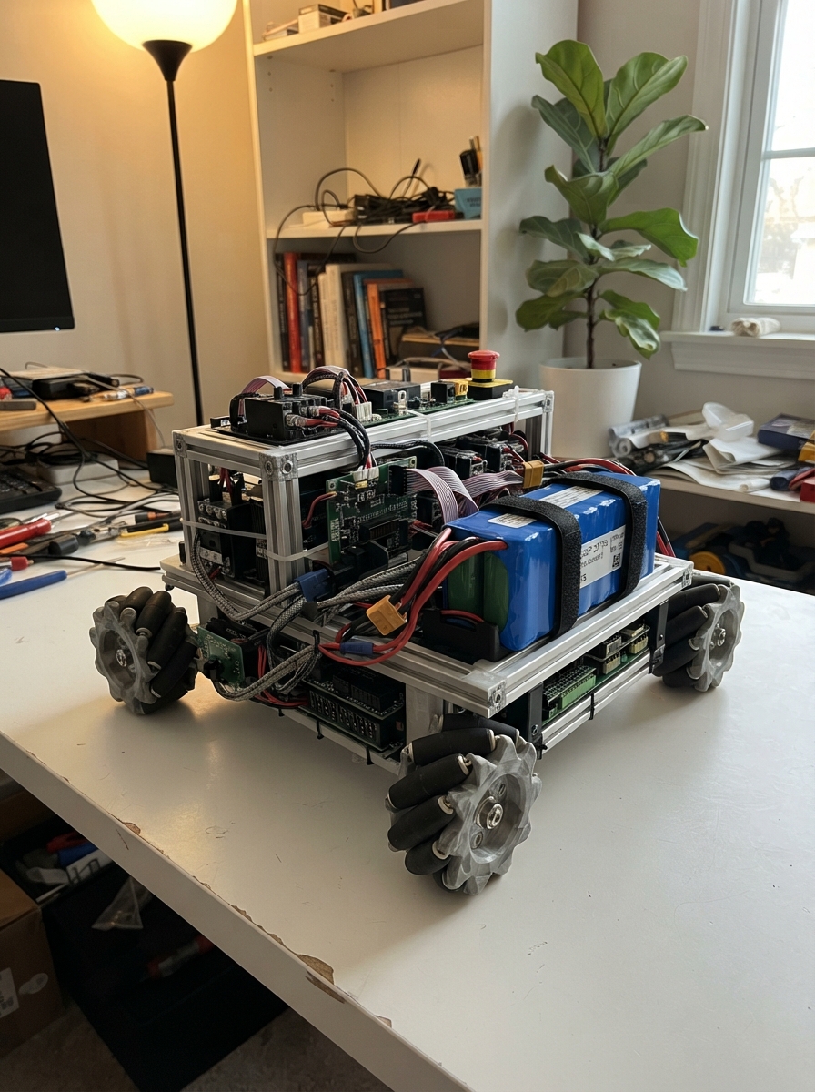
This guide builds a self-balancing inventory robot on Mecanum wheels, powered by a 48 V lithium-ion battery pack and driven by a sensored BLDC motor through a high-performance FOC controller. The robot uses a 6-axis IMU to detect tilt and maintain balance, with an ESP32 managing the sensor feedback, motor commands, and safety interlocks.
The assembly covers the complete high-voltage power path from battery through fused disconnect, precharge circuit, and main contactor, then the low-voltage control wiring for the IMU, motor controller, and enable switches. Readers will receive a full wiring diagram, parts list with specifications, firmware source code, and step-by-step assembly instructions that culminate in safe commissioning procedures.
Wiring diagram

Gather all the parts
Assemble it in 7 steps
1. Build the protected battery enclosure
Have a qualified battery-pack builder assemble battery_13s5p as a 13-series, 5-parallel 21700 pack with welded interconnects, insulation, a rigid enclosure, and strain relief. Connect its B+ and B− leads and the complete cell-group sense harness to bms_13s_250a exactly in the BMS maker’s specified order.
- A 13S pack is 54.6 V when fully charged; label it as hazardous DC.
- Keep the cell sense connector unplugged until the BMS instructions say it is time to connect it.
- A reversed or misordered BMS cell-sense lead can destroy the BMS and can start a battery fire.
- Do not assemble or test a high-energy lithium pack on a wooden bench or near flammable materials.
2. Install the high-current protection path
Bolt battery_13s5p positive to main_fuse IN using properly crimped, insulated high-current cable. Bolt main_fuse OUT to main_contactor BAT+, and main_contactor LOAD+ to vesc_75_300 B+. Bolt the protected battery negative path through bms_13s_250a P− to vesc_75_300 B−. Mount main_fuse, main_contactor, and vesc_75_300 on non-flammable, vibration-resistant supports with covered terminals.
- Use cable, lugs, torque values, and terminal covers rated for the expected fault current and at least 80 VDC.
- Keep positive and negative traction cables close together to reduce electrical noise.
- Never work on this path while the pack is connected; 54.6 V at this pack’s available current can melt tools and cause severe burns.
- A fuse is not a switch: disconnect the battery before changing any high-current wiring.
3. Add precharge and the emergency stop
Wire precharge_module from main_fuse OUT to vesc_75_300 B+ so its guarded momentary switch can fill the controller’s capacitors before the contactor closes. Wire estop_nc in series between main_fuse OUT and main_contactor COIL+. Wire main_contactor COIL− to contactor_driver LOAD−, then wire contactor_driver HV_GND to bms_13s_250a P−.
- Put the emergency-stop button where a standing operator can hit it without reaching across the wheel.
- Use the precharge switch only briefly before enabling the contactor; it is not a continuous-power switch.
- Bypassing precharge can damage the controller, contactor, or battery connectors through an inrush spark.
- The emergency stop must physically remove contactor-coil power even if the ESP32 freezes.
4. Wire the low-voltage controls
Connect dc_dc_48v_5v VIN+ to main_fuse OUT and VIN− to bms_13s_250a P−. Connect its 5 V output to the ESP32 VIN and its output ground to ESP32 GND. Connect contactor_driver IN to ESP32 GPIO25 and LOGIC_GND to ESP32 GND. Connect arm_enable_switch OUT to GPIO32 and its other side to GND so the code’s internal pull-up reads LOW when the key is enabled.
- Keep the small logic wires physically separate from the motor-phase cables.
- Mount the keyed enable switch where it cannot be bumped on.
- Do not feed the ESP32 directly from the traction pack; it will be destroyed.
- Make sure the DC-DC converter polarity is correct before plugging in the ESP32.
5. Mount and wire the balance sensor
Rigidly mount mpu6050_1 near the robot’s center structure with its board axes recorded. Wire VIN to 3V3 (power), GND to GND (ground), SDA to GPIO21 (data), SCL to GPIO22 (clock), and INT to GPIO27 (signal). Do not mount it on a flexible camera or arm bracket.
- Mark the robot’s forward direction on the IMU mount; the later balance controller needs that exact orientation.
- Use short twisted I2C wires if the controller enclosure is electrically noisy.
- A loose or misoriented IMU produces incorrect tilt data and can make a balancing robot accelerate in the wrong direction.
6. Connect the motor controller and wheel motor
With the battery disconnected, connect vesc_75_300 U, V, and W to wheel_motor U, V, and W. Connect the Hall supply, Hall ground, and Hall A/B/C wires pin-for-pin between wheel_motor and vesc_75_300. Connect VESC UART TX to ESP32 GPIO16 (data), UART RX to GPIO17 (data), and UART GND to ESP32 GND (ground).
- Route the Hall and UART wires away from the three thick motor-phase wires.
- Use a mechanically guarded test stand that leaves the wheel off the floor for all controller setup.
- Motor phase wires can move or heat suddenly if the controller is misconfigured; keep hands, hair, tools, and loose clothing away from the wheel.
- Do not test balancing with the 5-foot structure free-standing; use a tethered rig or rigid overhead restraint.
7. Commission without a rider or free balancing
Start with the emergency stop released, the key off, and the wheel restrained. Press the precharge switch briefly, then turn the key on only after the ESP32 serial status says the IMU is online and the robot is within the allowed tilt angle. Verify that pressing the emergency stop opens the contactor immediately. Keep the supplied firmware unchanged: it only supervises contactor permission and does not command motor torque.
- Have a second adult operate the emergency stop during early testing.
- Configure motor-current and battery-current limits in the VESC conservatively before any restrained spin test.
- This submitted project is not a balancing controller and must not be used to attempt a free-standing balance test.
- A 40 lb, 5-foot robot can fall with serious force; use a test enclosure, tether, and an operator safety plan before adding torque control.
Review all connections
1. Connections between "battery_13s5p" and "ESP32"
2. Connections between "bms_13s_250a" and "ESP32"
3. Connections between "main_fuse" and "ESP32"
4. Connections between "precharge_module" and "ESP32"
5. Connections between "main_contactor" and "ESP32"
6. Connections between "estop_nc" and "ESP32"
7. Connections between "contactor_driver" and "ESP32"
8. Connections between "dc_dc_48v_5v" and "ESP32"
9. Connections between "vesc_75_300" and "ESP32"
10. Connections between "wheel_motor" and "ESP32"
11. Connections between "mpu6050_1" and "ESP32"
12. Connections between "arm_enable_switch" and "ESP32"
Deploy the firmware
#include <Arduino.h>
#include <Wire.h>
#include <MPU6050.h>

constexpr int CONTACTOR_ENABLE_PIN = 25;
constexpr int KEY_ENABLE_PIN = 32;
constexpr int IMU_INT_PIN = 27;
constexpr int VESC_RX_PIN = 16;
constexpr int VESC_TX_PIN = 17;
constexpr int I2C_SDA_PIN = 21;
constexpr int I2C_SCL_PIN = 22;

constexpr float MAX_ARM_ANGLE_DEG = 10.0f;
constexpr uint32_t STABLE_TIME_MS = 2000;
constexpr uint32_t STATUS_INTERVAL_MS = 500;

MPU6050 imu;
HardwareSerial vescSerial(2);

bool imuReady = false;
bool contactorClosed = false;
uint32_t stableSinceMs = 0;
uint32_t lastStatusMs = 0;

float readPitchDegrees() {
  int16_t ax, ay, az, gx, gy, gz;
  imu.getMotion6(&ax, &ay, &az, &gx, &gy, &gz);
  const float axf = static_cast<float>(ax);
  const float ayf = static_cast<float>(ay);
  const float azf = static_cast<float>(az);
  return atan2f(ayf, sqrtf(axf * axf + azf * azf)) * 180.0f / PI;
}

void setContactor(bool close) {
  digitalWrite(CONTACTOR_ENABLE_PIN, close ? HIGH : LOW);
  contactorClosed = close;
}

void setup() {
  pinMode(CONTACTOR_ENABLE_PIN, OUTPUT);
  setContactor(false);
  pinMode(KEY_ENABLE_PIN, INPUT_PULLUP);
  pinMode(IMU_INT_PIN, INPUT);

  Serial.begin(115200);
  vescSerial.begin(115200, SERIAL_8N1, VESC_RX_PIN, VESC_TX_PIN);
  Wire.begin(I2C_SDA_PIN, I2C_SCL_PIN);
  Wire.setClock(400000);

  imu.initialize();
  imuReady = imu.testConnection();
  Serial.println(imuReady ? "IMU online; traction remains disabled." : "IMU not found; traction locked out.");
}

void loop() {
  const uint32_t now = millis();
  const bool keyEnabled = digitalRead(KEY_ENABLE_PIN) == LOW;
  bool upright = false;
  float pitchDeg = 0.0f;

  if (imuReady) {
    pitchDeg = readPitchDegrees();
    upright = fabsf(pitchDeg) <= MAX_ARM_ANGLE_DEG;
  }

  if (keyEnabled && upright) {
    if (stableSinceMs == 0) {
      stableSinceMs = now;
    }
    if (now - stableSinceMs >= STABLE_TIME_MS) {
      setContactor(true);
    }
  } else {
    stableSinceMs = 0;
    setContactor(false);
  }

  // This project is an electrical and safety architecture only. Do not add
  // VESC torque commands here until the restrained balance controller has
  // been designed and independently tested.
  if (now - lastStatusMs >= STATUS_INTERVAL_MS) {
    lastStatusMs = now;
    Serial.printf("pitch=%.1f deg, key=%s, contactor=%s\n", pitchDeg,
                  keyEnabled ? "on" : "off", contactorClosed ? "closed" : "open");
  }

  delay(10);
}
Remix this project
Make it yours in one click
Open a full copy of this project in your own Schematik workspace — diagram, code, parts, and assembly steps included. Swap the sensor, add features, or redesign the whole thing with AI. The author's original stays untouched.