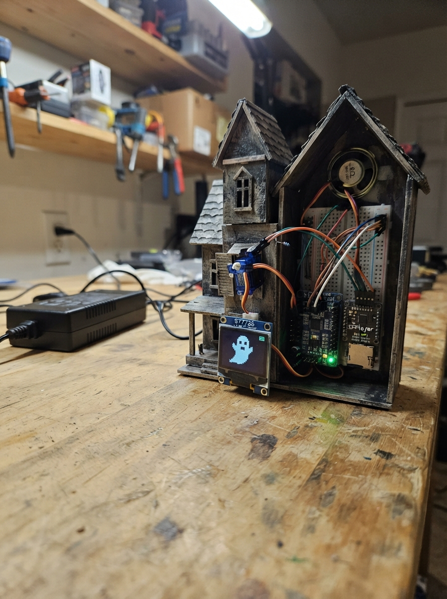
This haunted house diorama combines animated graphics, servo-driven mechanics, and spooky sound effects to create an interactive display. Two 1.8-inch TFT screens show morphing portraits and flickering fire animations while seven servos animate physical scenery elements, all synchronized with audio playback through a speaker.
Builders will receive a complete wiring diagram, parts list, and firmware that handles screen rendering, servo control via the PCA9685 driver, and MP3 audio playback. The guide covers power distribution from a single 5V 10A supply, calibration of servo travel ranges, and step-by-step assembly to bring the diorama to life.
Wiring diagram
Gather all the parts
Assemble it in 6 steps
1. Prepare the two screens
Use two 1.8-inch 128×160 ST7735R non-IPS TFT modules with backlight circuitry onboard. Fire goes behind the fireplace; portrait behind a picture frame. Both share GPIO11 (image data) and GPIO12 (clock). Fire CS → GPIO10, DC → GPIO4, RST → GPIO5. Portrait CS → GPIO14, DC → GPIO6, RST → GPIO7. VCC and BLK → 3V3; GND → GND. Leave MISO disconnected.
- The included portrait is stylized drawn artwork, not a photographic painting. Check viewing angle before mounting non-IPS panels.
- Firmware uses INITR_BLACKTAB. A module with shifted or incorrect colors may need its matching ST7735 initialization option.
2. Connect the servo controller
PCA9685 VCC → 3V3 (logic power), SDA → GPIO8 (data), SCL → GPIO9 (clock), GND and OE → GND. Leave address jumpers open for address 0x40. Connect servo signals to channels 0–6 in order.
- Do not connect PCA9685 VCC to 5 V: that would pull the ESP32 data wires above their safe voltage.
3. Connect the single 5 V 10 A supply
With all power unplugged, connect supply1 +5V to a covered distribution point using wire and connectors rated for at least 10 A. Run separate branches to the seven servo red wires, PCA9685 V+, and DFPlayer VCC. Return all servo grounds and DFPlayer GND directly to the supply-negative distribution point; also connect PCA9685 GND and ESP32 GND there for the signal reference. Do not route combined servo current through the PCA9685 board or a solderless breadboard. Servo signal wires still go to PCA9685 channels 0–6. Put the 2200 µF, 10 V capacitor close to the driver: + to the 5 V distribution branch and striped minus to GND. Keep the DFPlayer power branch separate from the servo branches back to the supply to reduce motor noise.
- Use regulated 5 V DC only; check voltage and polarity before connecting electronics. The 10 A rating is available capacity, not current forced into each device.
- Never connect external +5 V to ESP32 5V, USB, or 3V3. USB powers only the board and displays; the grounds must still join.
- A 10 A supply can overheat thin wires during a short. Use insulated, properly rated distribution wiring and a current-limited or short-circuit-protected supply. Never work on exposed mains terminals; an open-frame supply must be safely enclosed by a qualified person.
- Reverse capacitor polarity can make it burst. The capacitor reduces brief voltage dips but cannot fix an overloaded supply or jammed servo.
4. Add sound
GPIO17 → 1 kΩ resistor → DFPlayer RX (sound commands). DFPlayer TX → 1 kΩ tx_top resistor → GPIO18. Connect the 2 kΩ tx_bottom resistor from GPIO18 to GND; this divider protects the ESP32 input. Connect an 8Ω 3W speaker across SPK1 and SPK2, not ground. Insert a FAT32 microSD card, 32 GB or smaller, into DFPlayer with a combined haunted music and fire crackle recording named /mp3/0001.mp3. It repeats continuously. Audio is supplied by you; Deploy cannot write this card.
- A single DFPlayer cannot mix two recordings. Combine the sounds into one file before copying it to the card. Start at modest volume.
5. Fit and test moving scenery
First test all seven servos without horns or linkages. Channels 0–3 operate windows, channel 4 the door, and channels 5–6 other props. Firmware moves one channel at a time through a small 1400–1600 microsecond range. Mount horns only after noting the closed position, then adjust each closedUs/openUs value for your mechanism. Use light scenery and flexible links; provide mechanical clearance. Servos release after each movement, so props must rest safely without motor holding force.
- Keep fingers away from linkages. Stop power immediately if a servo buzzes, jams, or gets hot. Never increase travel against a physical stop.
6. Double-check the separate power rails
The checker flags the driver's 5 V servo rail, but its logic VCC must remain 3.3 V as wired. V+ supplies motors only. GPIO14 is a normal digital chip-select output. The external 5 V supply does not feed the ESP32 board; USB powers the board and screens. Confirm these connections before switching on.
Review all connections
1. Connections between "fire" and "ESP32"
2. Connections between "portrait" and "ESP32"
3. Connections between "driver" and "ESP32"
4. Connections between "audio" and "ESP32"
5. Connections between "rx_resistor" and "ESP32"
6. Connections between "servo0" and "ESP32"
7. Connections between "servo1" and "ESP32"
8. Connections between "servo2" and "ESP32"
9. Connections between "servo3" and "ESP32"
10. Connections between "servo4" and "ESP32"
11. Connections between "servo5" and "ESP32"
12. Connections between "servo6" and "ESP32"
13. Connections between "supply1" and "ESP32"
14. Connections between "bulk" and "ESP32"
15. Connections between "tx_top" and "ESP32"
16. Connections between "tx_bottom" and "ESP32"
Deploy the firmware
#include <Arduino.h>
#include <SPI.h>
#include <Wire.h>
#include <Adafruit_GFX.h>
#include <Adafruit_ST7735.h>
#include <Adafruit_PWMServoDriver.h>
#include <DFRobotDFPlayerMini.h>
#include <math.h>
Adafruit_ST7735 fire(10,4,5), portrait(14,6,7);
Adafruit_PWMServoDriver pwm(0x40);
DFRobotDFPlayerMini audio;
HardwareSerial music(1);
GFXcanvas16 canvas(128,160), lady(128,160), bones(128,160);
bool servoReady=false, moving=false;
// Conservative starting travel. Calibrate with linkages disconnected.
const uint16_t closedUs[7]={1400,1400,1400,1400,1400,1400,1400};
const uint16_t openUs[7]={1600,1600,1600,1600,1600,1600,1600};
int activeServo=0, lastMorph=-1;
uint32_t lastFire=0,lastPortrait=0,lastServo=0;
uint16_t rgb(int r,int g,int b){return ((r&248)<<8)|((g&252)<<3)|(b>>3);}
void makePortrait(GFXcanvas16 &c,bool skull){
 c.fillScreen(rgb(21,12,18));
 for(int i=0;i<5;i++) c.drawRect(i+3,i+3,122-2*i,154-2*i,rgb(145-i*17,100-i*12,32));
 c.fillTriangle(20,146,64,87,108,146,rgb(37,22,48));
 c.fillCircle(64,95,14,rgb(46,28,55));
 c.fillCircle(64,53,30,rgb(39,22,17));
 c.fillCircle(39,66,12,rgb(39,22,17));c.fillCircle(89,66,12,rgb(39,22,17));
 c.fillRoundRect(44,40,40,48,18,skull?rgb(209,203,167):rgb(211,163,129));
 if(!skull){
  c.fillCircle(54,59,2,0);c.fillCircle(74,59,2,0);
  c.drawLine(64,61,61,70,rgb(145,95,78));
  c.drawLine(57,77,71,77,rgb(130,39,49));
  c.fillTriangle(47,91,64,105,81,91,rgb(210,201,180));
 }else{
  c.fillCircle(54,59,7,0);c.fillCircle(74,59,7,0);
  c.fillTriangle(64,67,60,74,68,74,0);
  c.fillRect(52,78,25,8,rgb(220,213,177));
  for(int x=54;x<78;x+=5)c.drawFastVLine(x,78,8,0);
  c.drawFastVLine(64,94,44,rgb(214,208,176));
  for(int y=105;y<134;y+=7){c.drawLine(64,y,45,y-4,rgb(214,208,176));c.drawLine(64,y,83,y-4,rgb(214,208,176));}
 }
 c.fillCircle(64,104,3,rgb(160,25,35));
}
void drawFire(){
 canvas.fillScreen(0);
 // Vary each flame independently; buffer prevents visible clearing flicker.
 for(int x=4;x<124;x+=6){
  int h=random(25,100), tip=x+random(-8,9);
  canvas.fillTriangle(x-9,145,x+9,145,tip,145-h,rgb(205+random(50),random(30,95),0));
  canvas.fillTriangle(x-4,145,x+5,145,tip,150-h/2,rgb(255,160+random(80),15));
 }
 canvas.fillRoundRect(12,140,80,10,4,rgb(72,28,10));
 canvas.fillRoundRect(40,149,76,8,4,rgb(83,33,12));
 fire.drawRGBBitmap(0,0,canvas.getBuffer(),128,160);
}
void drawPortrait(int mix){
 uint16_t *out=canvas.getBuffer(),*a=lady.getBuffer(),*b=bones.getBuffer();
 for(int i=0;i<128*160;i++){
  int r=(((a[i]>>11)&31)*(32-mix)+((b[i]>>11)&31)*mix)/32;
  int g=(((a[i]>>5)&63)*(32-mix)+((b[i]>>5)&63)*mix)/32;
  int bl=((a[i]&31)*(32-mix)+(b[i]&31)*mix)/32;
  out[i]=(r<<11)|(g<<5)|bl;
 }
 portrait.drawRGBBitmap(0,0,out,128,160);
}
void setup(){
 Serial.begin(115200);
 pinMode(10,OUTPUT);digitalWrite(10,HIGH);pinMode(14,OUTPUT);digitalWrite(14,HIGH);
 SPI.begin(12,-1,11);
 fire.initR(INITR_BLACKTAB);portrait.initR(INITR_BLACKTAB);
 makePortrait(lady,false);makePortrait(bones,true);
 drawPortrait(0);lastMorph=0;
 Wire.begin(8,9);
 servoReady=pwm.begin();
 if(servoReady){pwm.setPWMFreq(50);for(int i=0;i<16;i++)pwm.setPWM(i,0,4096);}
 else Serial.println("PCA9685 missing: check power and I2C wiring.");
 // Module TX returns through a 1k/2k voltage divider.
 music.begin(9600,SERIAL_8N1,18,17);
 audio.begin(music,false,false);
 delay(1500);audio.volume(16);audio.playMp3Folder(1);delay(150);audio.enableLoop();
 Serial.println("Haunted house running. Audio commands sent; check card and speaker for playback.");
}
void loop(){
 uint32_t now=millis();
 if(now-lastFire>=80){lastFire=now;drawFire();}
 if(now-lastPortrait>=100){
  lastPortrait=now;uint32_t t=now%24000;int m;
  if(t<8000)m=0;else if(t<12000)m=(t-8000)*32/4000;
  else if(t<20000)m=32;else m=32-(t-20000)*32/4000;
  if(m!=lastMorph){drawPortrait(m);lastMorph=m;}
 }
 // One prop moves at a time. Channels 0..3 windows, 4 door, 5..6 objects.
 if(servoReady && now-lastServo>=20){
  lastServo=now;uint32_t slot=now%21000;activeServo=slot/3000;
  uint32_t t=slot%3000;
  if(t<2200){
   float f=(1.0f-cosf(6.2831853f*t/2200.0f))/2;
   pwm.writeMicroseconds(activeServo,closedUs[activeServo]+int((openUs[activeServo]-closedUs[activeServo])*f));
  }else pwm.setPWM(activeServo,0,4096); // release prop, reduce heating
 }
}
// Wiring reviewed: GPIO18 is the junction of tx_top.P2 and tx_bottom.P1.
// GPIO14 is software-controlled CS, not a fixed SPI peripheral signal.
// PCA9685 VCC is 3.3V; its separate 5V V+ rail never sets I2C logic voltage.
Remix this project
Make it yours in one click
Open a full copy of this project in your own Schematik workspace, diagram, code, parts, and assembly steps included. Swap the sensor, add features, or redesign the whole thing with AI. The author's original stays untouched.