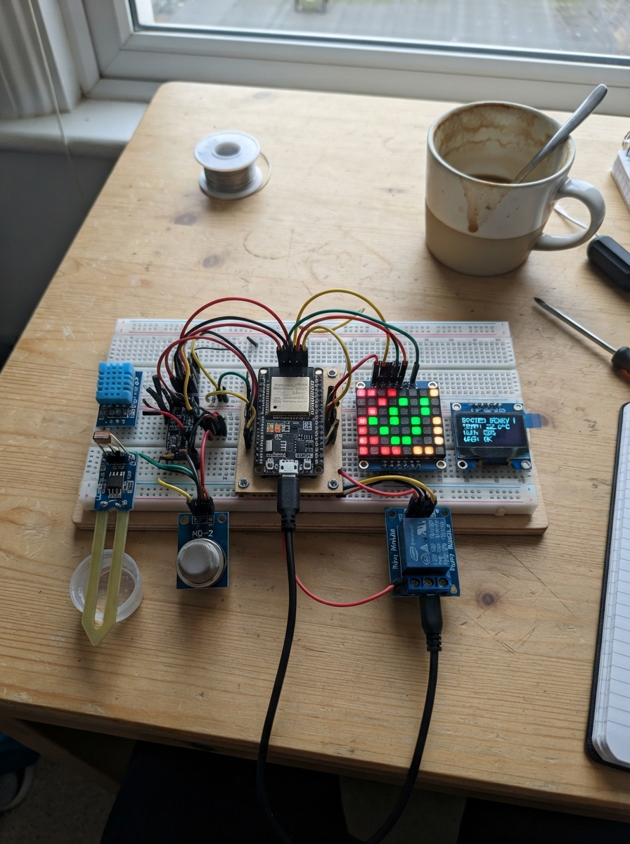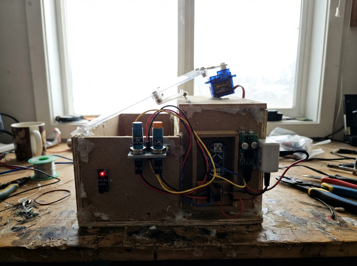
This smart waste sorting bin uses multiple sensor technologies to automatically identify and sort different materials. An ESP32 microcontroller coordinates three specialized sensors—an inductive sensor for metals, a capacitive sensor for paper, and an IR sensor for plastics—to detect what type of waste is approaching. When an item is identified, a servo motor rotates a diverter gate to direct the waste into the appropriate bin compartment.
This guide provides a complete wiring diagram, detailed parts list, and step-by-step assembly instructions to build a working prototype. The included firmware handles sensor debouncing, material classification logic, and servo control timing. Builders will learn how to integrate multiple sensor types with an ESP32, manage power distribution for mixed voltage requirements, and implement reliable object detection and sorting routines.
Wiring diagram
Gather all the parts
Assemble it in 8 steps
1. Keep power disconnected while rewiring
Unplug the ESP32 USB cable and switch off the 12 V adapter. Remove the MG996R horn from the servo for this first test, so a wrong angle cannot force the mechanism or trap your fingers.
- Do not let the heavy servo push against a hard stop; it can draw enough current to overheat wires or damage the power converter.
2. Set the servo supply to 5 V
Connect adapter positive to buck VIN+ and adapter negative to VIN-. Before connecting the MG996R, adjust the buck converter with a multimeter so VOUT+ measures exactly 5.0 V relative to VOUT-. Connect the MG996R red wire to VOUT+ (power), and its brown wire to VOUT- (ground). The buck converter must be rated for at least 3 A at 5 V for this high-torque servo.
- Do not connect the servo red wire to the ESP32 3V3 or 5V pin; the board cannot safely supply the servo current.
3. Add the shared ground and smoothing capacitor
Connect buck VOUT- to an ESP32 GND pin (shared ground). Connect cap positive to the buck 5 V output and cap negative, the striped lead, to buck ground near the servo (power smoothing).
- Make sure the capacitor striped negative lead goes to ground; reversed capacitor polarity can rupture the capacitor.
4. Connect the MG996R control wire
Connect the MG996R orange wire to ESP32 GPIO33 (movement control). The MG996R lead colors are brown for ground, red for 5 V power, and orange for the control wire.
- Keep the orange signal lead away from the servo's red and brown power pair where possible.
5. Check the metal sensor connection
Keep the LJ18A3 sensor brown wire on the 12 V sensor supply (power), its blue wire on ground (ground), and its black wire connected through the existing PC817 optocoupler. The optocoupler output collector goes to ESP32 GPIO25 (metal-detection signal), with the existing 10 kΩ resistor pulling it up to 3V3.
- Do not connect the LJ18A3 black output wire directly to an ESP32 pin; its 12 V sensor circuit can damage the 3.3 V ESP32 input.
6. Place the paper detector
Power the FC-51 from ESP32 3V3 (power) and GND (ground). Connect its OUT pin to GPIO27 (paper-detection signal). Point its two front sensors at the paper path, then turn its small adjustment screw until its indicator changes only when paper passes in front of it.
- Use plain white paper for the first adjustment. Very dark, shiny, or transparent paper can need a different sensor position or sensitivity setting.
- Keep the FC-51 at 3.3 V in this project; do not power it from 5 V because its OUT signal could then be too high for the ESP32 input.
7. Wire the new IR sensor
Connect the TCRT5000 VCC pin to ESP32 3V3 (power), GND to ESP32 GND (ground), and DO to GPIO32 (detection signal). Put the sensor 1 to 25 mm from the paper or object surface, then turn its small adjustment screw until its indicator changes at the distance you need.
- Use the DO pin only; leave AO unconnected. Test with the actual paper or object because color and shine change how infrared light reflects.
- Keep this module on 3.3 V so its DO signal stays safe for the ESP32 input; do not connect a 5 V signal to GPIO32.
8. Test all three detectors separately
Turn on the 12 V adapter and plug the ESP32 into USB. Keep the servo horn unloaded. Test metal at the LJ18A3, paper at the FC-51, then an object at the new TCRT5000. Any one detector moves the servo to 135 degrees for 5 seconds, then it returns to 90 degrees. Move every detected item away before the next test.
- Stop power if the servo chatters continuously, gets hot, or pushes against a hard mechanical stop.
Review all connections
1. Connections between "adapter" and "ESP32"
2. Connections between "buck" and "ESP32"
3. Connections between "servo" and "ESP32"
4. Connections between "cap" and "ESP32"
5. Connections between "ir" and "ESP32"
6. Connections between "metal" and "ESP32"
7. Connections between "limit_m" and "ESP32"
8. Connections between "opto_m" and "ESP32"
9. Connections between "pull_m" and "ESP32"
10. Connections between "plastic" and "ESP32"
11. Connections between "limit_p" and "ESP32"
12. Connections between "opto_p" and "ESP32"
13. Connections between "pull_p" and "ESP32"
14. Connections between "ir_extra" and "ESP32"
Deploy the firmware
#include <Arduino.h>

constexpr int SERVO_PIN = 33;
constexpr int METAL_SENSOR_PIN = 25;
constexpr int PAPER_SENSOR_PIN = 27;
// TCRT5000 is adjusted to detect the plastic item at the sensing point.
constexpr int PLASTIC_IR_SENSOR_PIN = 32;
constexpr int REST_ANGLE = 90;
constexpr int METAL_DETECTED_ANGLE = 135;
constexpr uint32_t DEBOUNCE_MS = 40;
constexpr uint32_t METAL_HOLD_MS = 5000;
// The sensor must stay clear for this long before another metal detection can start a new cycle.
constexpr uint32_t REARM_CLEAR_MS = 500;

constexpr uint32_t SERVO_FREQUENCY_HZ = 50;
constexpr uint8_t SERVO_RESOLUTION_BITS = 16;
constexpr uint32_t SERVO_PERIOD_US = 20000;
constexpr uint32_t SERVO_MIN_PULSE_US = 1000;
constexpr uint32_t SERVO_MAX_PULSE_US = 2000;

bool objectDetected = false;
bool lastRawState = false;
bool servoAwayFromRest = false;
bool waitingForSensorsClear = false;
uint32_t rawStateChangedAt = 0;
uint32_t sensorsClearSince = 0;
uint32_t returnServoAt = 0;

void setServoAngle(int angle) {
  angle = constrain(angle, 0, 180);
  const uint32_t pulseUs = map(angle, 0, 180, SERVO_MIN_PULSE_US, SERVO_MAX_PULSE_US);
  const uint32_t maxDuty = (1UL << SERVO_RESOLUTION_BITS) - 1;
  const uint32_t duty = (pulseUs * maxDuty) / SERVO_PERIOD_US;
  ledcWrite(SERVO_PIN, duty);
}

void moveServoForDetectedItem() {
  setServoAngle(METAL_DETECTED_ANGLE);
  servoAwayFromRest = true;
  returnServoAt = millis() + METAL_HOLD_MS;
  Serial.println("Item detected: servo moved to 135 degrees for 5 seconds.");
}

void returnServoToRest() {
  setServoAngle(REST_ANGLE);
  servoAwayFromRest = false;
  Serial.println("Servo returned to 90 degrees.");
}

void setup() {
  Serial.begin(115200);
  delay(300);

  // The optocoupler pulls GPIO25 LOW when the inductive sensor sees metal.
  pinMode(METAL_SENSOR_PIN, INPUT_PULLUP);
  // The FC-51 pulls GPIO27 LOW when paper is in front of its sensor.
  pinMode(PAPER_SENSOR_PIN, INPUT_PULLUP);
  // The TCRT5000 pulls GPIO32 LOW when plastic reflects enough IR light.
  pinMode(PLASTIC_IR_SENSOR_PIN, INPUT_PULLUP);

  if (!ledcAttach(SERVO_PIN, SERVO_FREQUENCY_HZ, SERVO_RESOLUTION_BITS)) {
    Serial.println("Servo PWM could not start on GPIO33.");
  }

  lastRawState = digitalRead(METAL_SENSOR_PIN) == LOW ||
                 digitalRead(PAPER_SENSOR_PIN) == LOW ||
                 digitalRead(PLASTIC_IR_SENSOR_PIN) == LOW;
  objectDetected = lastRawState;
  rawStateChangedAt = millis();
  setServoAngle(REST_ANGLE);
  if (objectDetected) {
    moveServoForDetectedItem();
  } else {
    Serial.println("Servo is at the 90-degree rest position.");
  }
  Serial.println("Metal, paper, and plastic-IR sensors with MG996R servo are ready.");
}

void loop() {
  const bool rawObjectDetected = digitalRead(METAL_SENSOR_PIN) == LOW ||
                                 digitalRead(PAPER_SENSOR_PIN) == LOW ||
                                 digitalRead(PLASTIC_IR_SENSOR_PIN) == LOW;
  const uint32_t now = millis();

  if (rawObjectDetected != lastRawState) {
    lastRawState = rawObjectDetected;
    rawStateChangedAt = now;
  }

  if (lastRawState != objectDetected && now - rawStateChangedAt >= DEBOUNCE_MS) {
    objectDetected = lastRawState;
    if (!objectDetected) {
      sensorsClearSince = now;
    } else if (!waitingForSensorsClear && !servoAwayFromRest) {
      // Either sensor starts one fixed five-second cycle. A second sensor
      // detection during that cycle must not restart or extend the timer.
      moveServoForDetectedItem();
    }
  }

  if (waitingForSensorsClear && !objectDetected && now - sensorsClearSince >= REARM_CLEAR_MS) {
    waitingForSensorsClear = false;
    Serial.println("Sensors are clear; ready for the next item.");
  }

  if (servoAwayFromRest && static_cast<int32_t>(now - returnServoAt) >= 0) {
    returnServoToRest();
    waitingForSensorsClear = true;
    if (!objectDetected) {
      sensorsClearSince = now;
    }
  }

  delay(5);
}
Remix this project
Make it yours in one click
Open a full copy of this project in your own Schematik workspace, diagram, code, parts, and assembly steps included. Swap the sensor, add features, or redesign the whole thing with AI. The author's original stays untouched.