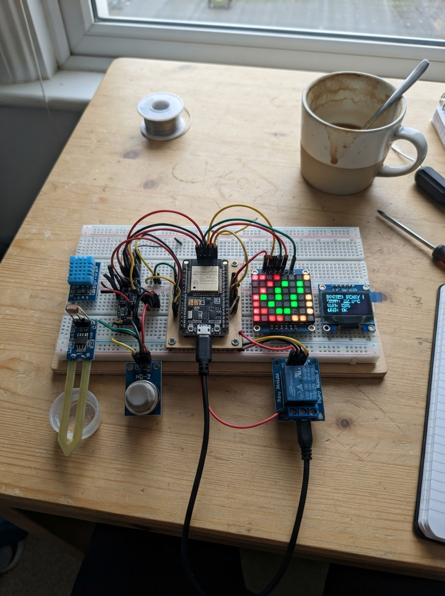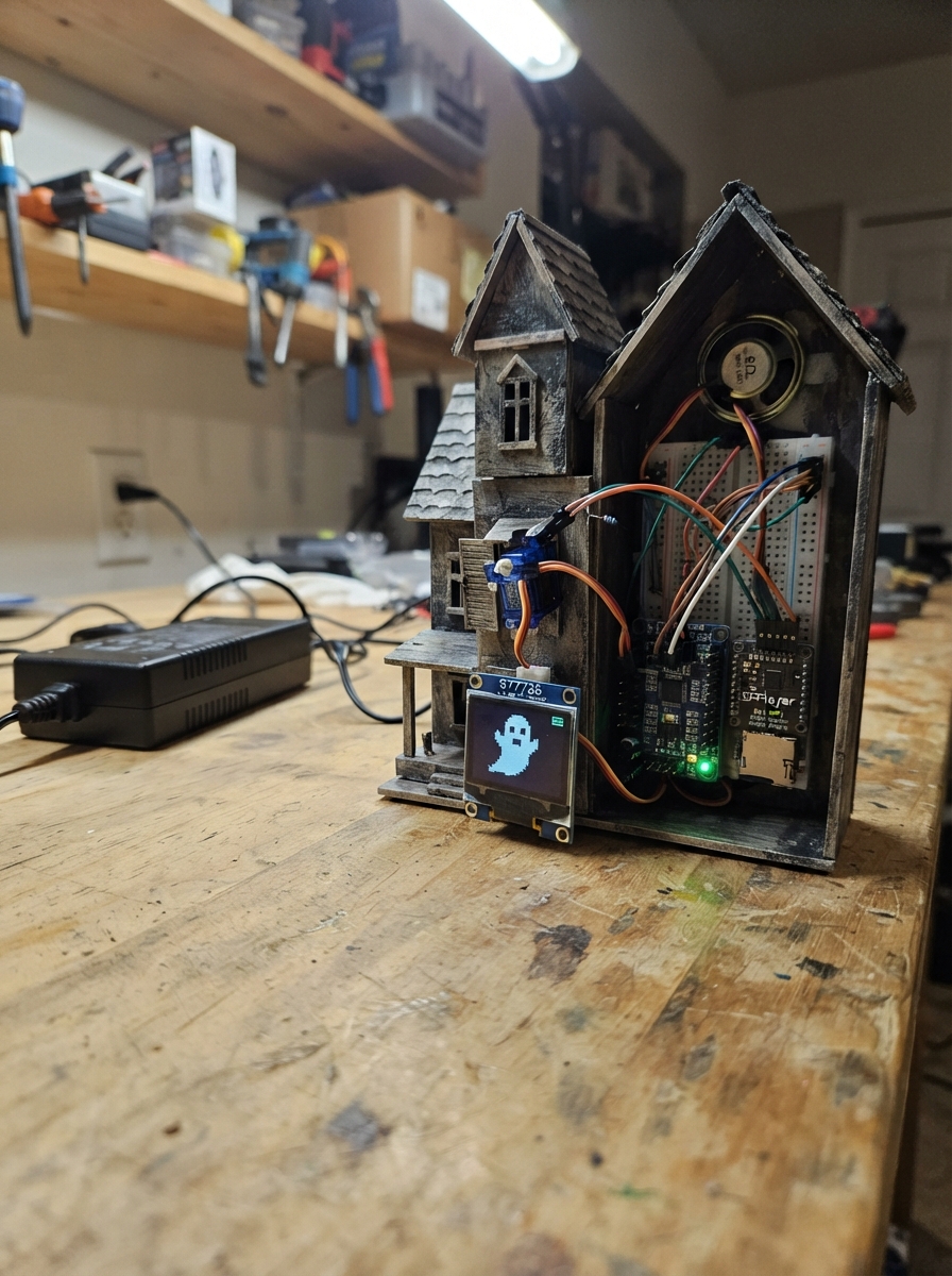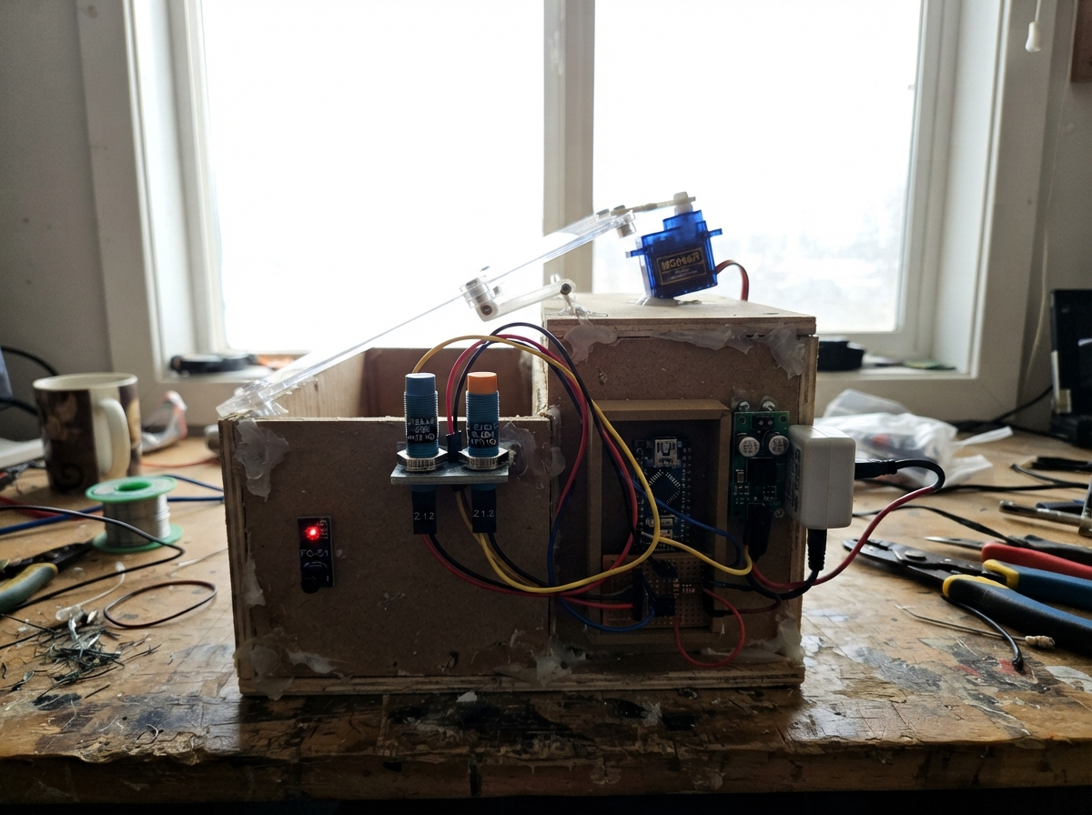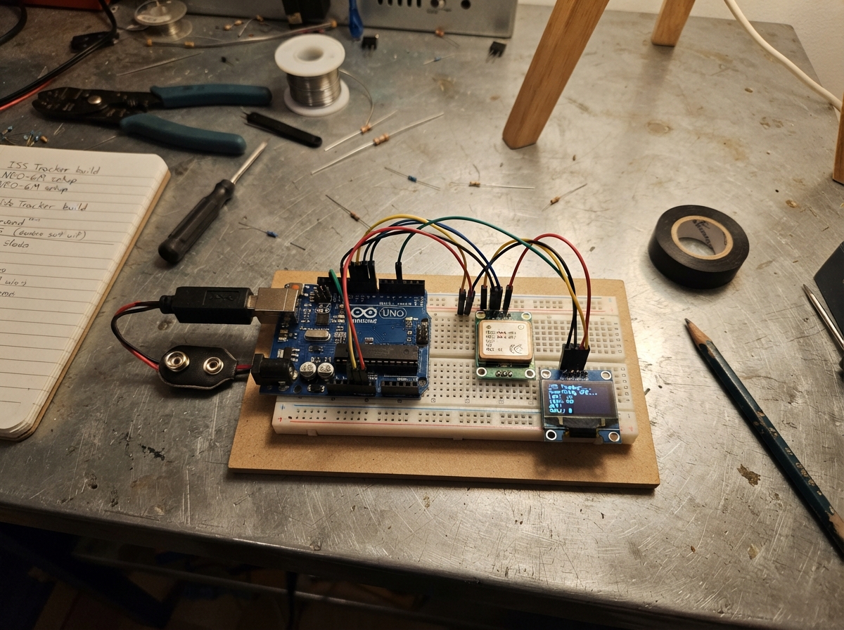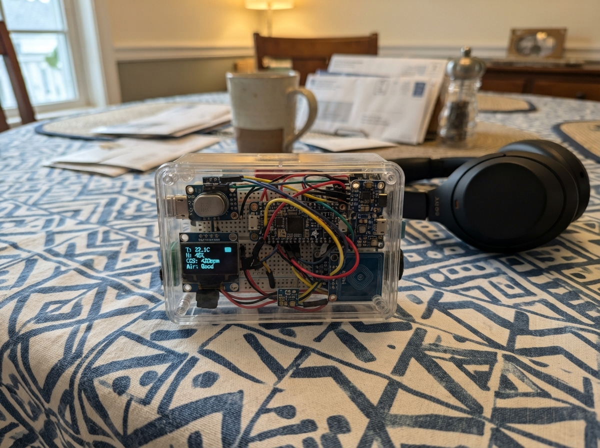
This pocket-sized multifunction device packs environmental sensing, air quality monitoring, motion tracking, NFC reading, audio playback, infrared transmission, and multiple light modes into a single ESP32-based tool. The guide provides a complete wiring diagram, parts list, and step-by-step assembly instructions for building a compact device that fits in a pocket while delivering professional-grade sensor data and utility features.
The firmware integrates nine different sensors and peripherals through I2C and I2S protocols, with a menu-driven OLED interface for navigating between environmental readings, motion data, NFC tag detection, audio playback, and torch modes. Builders will learn how to manage multiple sensor libraries, handle I2S audio I/O, control addressable outputs, and create an intuitive button-based navigation system on resource-constrained hardware.
Wiring diagram
Gather all the parts
Assemble it in 7 steps
1. Set up the power rails
Place the ESP32-S3 board across the centre gap of a breadboard. Run one red wire from its 3V3 pin to the red power rail and one black wire from GND to the blue ground rail. Every module in this build uses the 3.3 V rail; do not connect any module VCC pin to the board's 5 V pin.
- Use a powered USB port or a short USB cable because the PM and CO₂ sensors take noticeable current.
- Connecting a 3.3 V-only sensor or NFC module to 5 V can damage it.
2. Wire the shared sensor and display wires
Connect SDA from the BME680, SCD40, PMSA003I, BH1750, BNO055, PN532, and OLED to GPIO8 (data). Connect SCL from each of those same modules to GPIO9 (clock). Connect each module's VCC or VIN to 3V3 (power) and GND to GND (ground). On the BH1750, also connect ADDR to GND so it uses its normal address. Set both PN532 DIP switches to ON before powering it; this selects its I2C connection.
- Keep these shared wires short and use the same two breadboard rows or rails for each branch.
- Mount the PM sensor with its air inlet clear and keep the BME680 away from the warm ESP32 and speaker.
- Do not swap the OLED's VCC and GND pins; swapped power can damage the display.
3. Add the microphone and speaker
Connect INMP441 VDD to 3V3 (power), GND to GND (ground), SCK to GPIO4 (sound clock), WS to GPIO5 (sound timing), SD to GPIO6 (microphone signal), and L/R to GND (left-channel selection). Connect MAX98357A VIN to 3V3 (power), GND to GND (ground), BCLK to GPIO4 (shared sound clock), LRC to GPIO5 (shared sound timing), and DIN to GPIO7 (speaker sound data). Connect MAX98357A SPK+ to the speaker POS terminal and SPK- to the speaker NEG terminal.
- The speaker wires go only to SPK+ and SPK-; neither speaker terminal connects to GND.
- Keep the microphone physically away from the speaker to reduce feedback.
- Do not connect either MAX98357A speaker output to ground; that can damage the amplifier.
4. Build the infrared transmitter
Put the 1 kΩ resistor between GPIO14 and the BASE of the 2N2222 or BC547 transistor (control). Connect the transistor EMITTER to GND (ground). Connect its COLLECTOR to the short leg, called the cathode, of the infrared LED (switched negative). Connect the infrared LED long leg, called the anode, to one end of the 68 Ω resistor, then connect the other end of that resistor to 3V3 (power). Aim the clear infrared LED toward the appliance you want to test.
- Check the transistor's flat face against its own printed pin diagram: BC547 and 2N2222 versions can have different leg order.
- A phone camera can often show the otherwise invisible infrared LED flickering during a test.
- A reversed infrared LED will not transmit and may be damaged if driven hard.
5. Build the three torch lights
For the white torch, connect GPIO1 to one end of the 470 Ω resistor, connect its other end to the white LED long leg, and connect the short leg to GND. Repeat with GPIO2, a 470 Ω resistor, and the red LED. For the UV LED, connect GPIO3 through the 220 Ω resistor to its long leg, then connect its short leg to GND. The resistors limit current so the ESP32 pins and LEDs stay safe.
- The long LED leg is positive; if an LED does not light, first turn its direction around with power disconnected.
- Keep the UV LED behind a small front opening so it cannot shine into eyes accidentally.
- Never look directly into the UV LED or shine it at another person's eyes.
6. Add the three control buttons
For each small push button, place it so it straddles the breadboard centre gap. Connect one side of the Next button to GPIO15 and its opposite side to GND (page change). Connect one side of the Action button to GPIO16 and its opposite side to GND (scan or IR/tone action). Connect one side of the Torch button to GPIO17 and its opposite side to GND (torch mode).
- A button has two internally joined legs on each side; use legs from opposite sides, not two legs on the same side.
- The firmware enables internal pull-ups, so no extra button resistors are needed.
7. Make a pocket-safe layout
Before putting the circuit in a case, confirm that the OLED, PM air inlet, BME680 vent, microphone hole, speaker opening, NFC antenna face, infrared LED, and three torch LEDs remain exposed. Keep the BNO055 away from the speaker magnet, the ESP32 USB cable, and steel screws so its compass reading is less distorted.
- Use a non-metallic enclosure around the compass module, and calibrate the heading by slowly moving the finished device through several directions.
- The NFC antenna works best when a tag is held flat against its coil face.
Review all connections
1. Connections between "bme680_1" and "ESP32"
2. Connections between "scd40_1" and "ESP32"
3. Connections between "pm25_1" and "ESP32"
4. Connections between "light_1" and "ESP32"
5. Connections between "imu_1" and "ESP32"
6. Connections between "nfc_1" and "ESP32"
7. Connections between "oled_1" and "ESP32"
8. Connections between "mic_1" and "ESP32"
9. Connections between "audio_amp_1" and "ESP32"
10. Connections between "ir_base_resistor_1" and "ESP32"
11. Connections between "ir_transistor_1" and "ESP32"
12. Connections between "ir_led_resistor_1" and "ESP32"
13. Connections between "torch_white_resistor_1" and "ESP32"
14. Connections between "torch_white_1" and "ESP32"
15. Connections between "torch_red_resistor_1" and "ESP32"
16. Connections between "torch_red_1" and "ESP32"
17. Connections between "torch_uv_resistor_1" and "ESP32"
18. Connections between "torch_uv_1" and "ESP32"
19. Connections between "button_next_1" and "ESP32"
20. Connections between "button_action_1" and "ESP32"
21. Connections between "button_torch_1" and "ESP32"
Deploy the firmware
#include <Arduino.h>
#include <Wire.h>
#include <WiFi.h>
#include <math.h>
#include <driver/i2s.h>
#include <Adafruit_BME680.h>
#include <SparkFun_SCD4x_Arduino_Library.h>
#include <BH1750.h>
#include <Adafruit_BNO055.h>
#include <Adafruit_Sensor.h>
#include <Adafruit_PN532.h>
#include <Adafruit_GFX.h>
#include <Adafruit_SSD1306.h>
#include <IRremoteESP8266.h>
#include <IRsend.h>
#include <NimBLEDevice.h>

constexpr int I2C_SDA = 8;
constexpr int I2C_SCL = 9;
constexpr int I2S_BCLK = 4;
constexpr int I2S_WS = 5;
constexpr int MIC_DATA = 6;
constexpr int AMP_DATA = 7;
constexpr int IR_PIN = 14;
constexpr int WHITE_LED_PIN = 1;
constexpr int RED_LED_PIN = 2;
constexpr int UV_LED_PIN = 3;
constexpr int NEXT_BUTTON_PIN = 15;
constexpr int ACTION_BUTTON_PIN = 16;
constexpr int TORCH_BUTTON_PIN = 17;
constexpr uint8_t PM_I2C_ADDRESS = 0x12;

Adafruit_BME680 bme;
SCD4x scd4x;
BH1750 lightMeter;
Adafruit_BNO055 bno(55, 0x28, &Wire);
// This PN532 breakout is used in I2C mode; IRQ and reset are not wired.
Adafruit_PN532 nfc(0xFF, 0xFF, &Wire);
Adafruit_SSD1306 display(128, 64, &Wire, -1);
IRsend irsend(IR_PIN);

bool bmeReady = false;
bool scdReady = false;
bool bnoReady = false;
bool nfcReady = false;
uint8_t page = 0;
uint8_t torchMode = 0;
uint32_t lastSensorRead = 0;
uint32_t lastNfcRead = 0;
uint32_t lastButtonChange = 0;
float temperatureC = NAN;
float humidity = NAN;
float gasKohm = NAN;
uint16_t co2ppm = 0;
uint16_t pm25 = 0;
float lux = NAN;
float heading = NAN;
float roll = NAN;
float pitch = NAN;
float soundDbfs = NAN;
String nfcUid = "No tag";
String radioStatus = "Press ACT to scan";

bool pressed(int pin) {
  if (digitalRead(pin) == LOW && millis() - lastButtonChange > 180) {
    lastButtonChange = millis();
    return true;
  }
  return false;
}

void setTorch() {
  uint8_t white = 0;
  uint8_t red = 0;
  uint8_t uv = 0;
  if (torchMode == 1) white = 45;
  if (torchMode == 2) white = 120;
  if (torchMode == 3) white = 255;
  if (torchMode == 4) red = 100;
  if (torchMode == 5) uv = 80;
  ledcWrite(WHITE_LED_PIN, white);
  ledcWrite(RED_LED_PIN, red);
  ledcWrite(UV_LED_PIN, uv);
}

void startAudio() {
  i2s_config_t config = {};
  config.mode = (i2s_mode_t)(I2S_MODE_MASTER | I2S_MODE_TX | I2S_MODE_RX);
  config.sample_rate = 16000;
  config.bits_per_sample = I2S_BITS_PER_SAMPLE_32BIT;
  config.channel_format = I2S_CHANNEL_FMT_ONLY_LEFT;
  config.communication_format = I2S_COMM_FORMAT_STAND_I2S;
  config.intr_alloc_flags = 0;
  config.dma_buf_count = 8;
  config.dma_buf_len = 64;
  config.use_apll = false;
  config.tx_desc_auto_clear = true;
  config.fixed_mclk = 0;
  i2s_pin_config_t pins = {};
  pins.bck_io_num = I2S_BCLK;
  pins.ws_io_num = I2S_WS;
  pins.data_out_num = AMP_DATA;
  pins.data_in_num = MIC_DATA;
  i2s_driver_install(I2S_NUM_0, &config, 0, nullptr);
  i2s_set_pin(I2S_NUM_0, &pins);
  i2s_zero_dma_buffer(I2S_NUM_0);
}

void measureSound() {
  int32_t samples[128];
  size_t bytesRead = 0;
  i2s_read(I2S_NUM_0, samples, sizeof(samples), &bytesRead, 25 / portTICK_PERIOD_MS);
  int count = bytesRead / sizeof(int32_t);
  if (count < 1) return;
  double meanSquare = 0.0;
  for (int i = 0; i < count; ++i) {
    int32_t sample = samples[i] >> 8;
    meanSquare += (double)sample * (double)sample;
  }
  double rms = sqrt(meanSquare / count);
  soundDbfs = (float)(20.0 * log10((rms + 1.0) / 8388607.0) + 94.0);
}

void playTone() {
  const int sampleRate = 16000;
  const int frequency = 880;
  const int samples = sampleRate / 6;
  int32_t frame[32];
  for (int offset = 0; offset < samples; offset += 32) {
    for (int i = 0; i < 32; ++i) {
      float phase = 2.0f * PI * frequency * (offset + i) / sampleRate;
      frame[i] = (int32_t)(sinf(phase) * 500000000.0f);
    }
    size_t written = 0;
    i2s_write(I2S_NUM_0, frame, sizeof(frame), &written, portMAX_DELAY);
  }
  i2s_zero_dma_buffer(I2S_NUM_0);
}

bool readPm25() {
  Wire.requestFrom((int)PM_I2C_ADDRESS, 32);
  if (Wire.available() < 32) return false;
  uint8_t data[32];
  for (uint8_t i = 0; i < 32; ++i) data[i] = Wire.read();
  if (data[0] != 0x42 || data[1] != 0x4D) return false;
  pm25 = ((uint16_t)data[12] << 8) | data[13];
  return true;
}

void readSensors() {
  if (bmeReady && bme.performReading()) {
    temperatureC = bme.temperature;
    humidity = bme.humidity;
    gasKohm = bme.gas_resistance / 1000.0f;
  }
  if (scdReady && scd4x.readMeasurement()) {
    co2ppm = scd4x.getCO2();
  }
  readPm25();
  lux = lightMeter.readLightLevel();
  if (bnoReady) {
    sensors_event_t event;
    bno.getEvent(&event, Adafruit_BNO055::VECTOR_EULER);
    heading = event.orientation.x;
    roll = event.orientation.y;
    pitch = event.orientation.z;
  }
  measureSound();
}

void scanNfc() {
  if (!nfcReady) return;
  uint8_t uid[7];
  uint8_t uidLength = 0;
  if (nfc.readPassiveTargetID(PN532_MIFARE_ISO14443A, uid, &uidLength, 50)) {
    nfcUid = "UID ";
    for (uint8_t i = 0; i < uidLength; ++i) {
      if (uid[i] < 16) nfcUid += "0";
      nfcUid += String(uid[i], HEX);
    }
    nfcUid.toUpperCase();
  }
}

void scanRadios() {
  int wifiCount = WiFi.scanNetworks(false, true);
  if (wifiCount < 0) wifiCount = 0;
  NimBLEDevice::init("");
  NimBLEScan *scanner = NimBLEDevice::getScan();
  scanner->setActiveScan(true);
  NimBLEScanResults results = scanner->getResults(2000, false);
  int bleCount = results.getCount();
  scanner->clearResults();
  NimBLEDevice::deinit(true);
  WiFi.scanDelete();
  radioStatus = "WiFi " + String(wifiCount) + " BLE " + String(bleCount);
}

void drawScreen() {
  display.clearDisplay();
  display.setTextColor(SSD1306_WHITE);
  display.setTextSize(1);
  if (page == 0) {
    display.setCursor(0, 0); display.println("AIR QUALITY");
    display.printf("CO2: %u ppm\n", co2ppm);
    display.printf("PM2.5: %u ug/m3\n", pm25);
    display.printf("T: %.1f C  H: %.0f%%\n", temperatureC, humidity);
    display.printf("VOC gas: %.0f kOhm\n", gasKohm);
    display.println("BME gas is a VOC trend");
  } else if (page == 1) {
    display.setCursor(0, 0); display.println("LEVEL / SOUND");
    display.printf("Heading: %.0f deg\n", heading);
    display.printf("Roll: %.1f  Pitch: %.1f\n", roll, pitch);
    display.printf("Light: %.0f lux\n", lux);
    display.printf("Sound: %.0f dBFS*\n", soundDbfs);
    display.println("*relative; calibrate for dB");
  } else if (page == 2) {
    display.setCursor(0, 0); display.println("NFC / RADIO SCAN");
    display.println(nfcUid);
    display.println(radioStatus);
    display.println("ACT scans WiFi + BLE");
    display.println("Hold a tag near NFC pad");
  } else {
    display.setCursor(0, 0); display.println("TOOLS");
    const char *names[] = {"OFF", "WHITE LOW", "WHITE MID", "WHITE HIGH", "RED", "UV"};
    display.print("Torch: "); display.println(names[torchMode]);
    display.println("ACT: IR test + tone");
    display.println("Torch button changes mode");
    display.println("IR code: NEC 20DF10EF");
  }
  display.display();
}

void setup() {
  Serial.begin(115200);
  Wire.begin(I2C_SDA, I2C_SCL);
  pinMode(NEXT_BUTTON_PIN, INPUT_PULLUP);
  pinMode(ACTION_BUTTON_PIN, INPUT_PULLUP);
  pinMode(TORCH_BUTTON_PIN, INPUT_PULLUP);
  ledcAttach(WHITE_LED_PIN, 5000, 8);
  ledcAttach(RED_LED_PIN, 5000, 8);
  ledcAttach(UV_LED_PIN, 5000, 8);
  setTorch();
  irsend.begin();
  startAudio();
  display.begin(SSD1306_SWITCHCAPVCC, 0x3C);
  display.clearDisplay(); display.display();
  bmeReady = bme.begin(0x76, &Wire);
  lightMeter.begin(BH1750::CONTINUOUS_HIGH_RES_MODE, 0x23, &Wire);
  scdReady = scd4x.begin(Wire);
  if (scdReady) scdReady = scd4x.startPeriodicMeasurement();
  bnoReady = bno.begin();
  if (bnoReady) bno.setExtCrystalUse(true);
  nfc.begin();
  uint32_t version = nfc.getFirmwareVersion();
  nfcReady = version != 0;
  if (nfcReady) nfc.SAMConfig();
  drawScreen();
}

void loop() {
  bool changed = false;
  if (pressed(NEXT_BUTTON_PIN)) {
    page = (page + 1) % 4;
    changed = true;
  }
  if (pressed(TORCH_BUTTON_PIN)) {
    torchMode = (torchMode + 1) % 6;
    setTorch();
    changed = true;
  }
  if (pressed(ACTION_BUTTON_PIN)) {
    if (page == 2) scanRadios();
    if (page == 3) {
      irsend.sendNEC(0x20DF10EF, 32);
      playTone();
    }
    changed = true;
  }
  if (millis() - lastSensorRead >= 1000) {
    lastSensorRead = millis();
    readSensors();
    changed = true;
  }
  if (page == 2 && millis() - lastNfcRead >= 750) {
    lastNfcRead = millis();
    String before = nfcUid;
    scanNfc();
    if (before != nfcUid) changed = true;
  }
  if (changed) drawScreen();
  delay(10);
}
Remix this project
Make it yours in one click
Open a full copy of this project in your own Schematik workspace, diagram, code, parts, and assembly steps included. Swap the sensor, add features, or redesign the whole thing with AI. The author's original stays untouched.