Community project
Remote Aroma Diffuser Timer
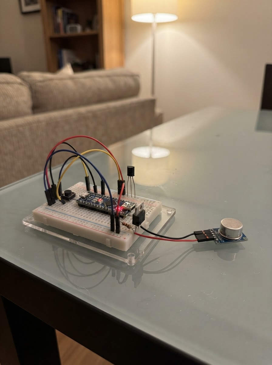
This project builds a smart aroma diffuser controller that runs mist cycles on a timer, controlled by either physical push buttons or an infrared remote. The ESP32 microcontroller manages a 5 V ultrasonic mist-maker module through a logic-level MOSFET switch, with debounced button inputs and IR command decoding to trigger 30, 60, or 120-minute diffusion sessions.
The guide provides a complete wiring diagram showing how to connect the push buttons, IR receiver, MOSFET gate circuit, and mist module to the ESP32, along with a full parts list, pre-written firmware, and step-by-step assembly instructions that emphasize keeping water away from electronics during construction and testing.
Wiring diagram

Gather all the parts
Assemble it in 5 steps
1. Keep the water and electronics separate
Mount the ESP32, IR receiver, MOSFET, resistors, and buttons in a dry enclosure. Put only the ultrasonic atomizer head/module in the diffuser water area as specified by its manufacturer.
- Use a strain-relieved cable between the dry electronics compartment and the mist module.
- Aim the IR receiver window toward the front of the enclosure.
- Use only a preassembled low-voltage 5 V mist-maker module. Keep water away from the ESP32, exposed wiring, and USB connector.
- Do not power a high-current mist module from a computer USB port; use a regulated 5 V USB supply rated for the module's specified current.
2. Wire the four local controls
Connect one terminal of each momentary button to ESP32 GND. Connect the other terminals as follows: ON/OFF button SIGNAL to GPIO32; 30-minute button SIGNAL to GPIO33; 1-hour button SIGNAL to GPIO26; 2-hour button SIGNAL to GPIO14. The firmware enables the ESP32’s internal pull-up resistors, so no external button resistors are required.
- A pressed button connects its GPIO to ground.
- Label the enclosure controls clearly: ON/OFF, 30 min, 1 hr, and 2 hr.
- Do not connect a button terminal to 5 V; the ESP32 GPIO pins are 3.3 V logic.
3. Wire the infrared receiver
With the VS1838B module’s pin labels checked against its own board printing, connect VCC to ESP32 3V3, GND to ESP32 GND, and OUT to GPIO27. Place the receiver behind a non-metal front window so the remote can see it.
- The pin order varies among bare VS1838B receivers and breakout boards—follow the labels, not the physical lead order.
- Power this receiver from 3.3 V in this design so its OUT signal is safe for the ESP32.
4. Build the MOSFET mist switch
Connect GPIO25 to one end of gate_resistor (220 Ω); connect its other end to the IRLZ44N GATE. Connect gate_pulldown (10 kΩ) from that GATE node to GND. Connect IRLZ44N SOURCE to GND. Connect IRLZ44N DRAIN to the mist_module GND/negative terminal. Connect mist_module VCC to the 5 V rail. Join the 5 V supply negative, ESP32 GND, and MOSFET SOURCE as one common ground.
- For a TO-220 IRLZ44N facing its marked flat side with leads downward, verify the GATE–DRAIN–SOURCE lead order from the actual part datasheet before soldering.
- The 10 kΩ pulldown keeps the mist module off while the ESP32 starts or is reset.
- Check the mist module current rating. This circuit is for a low-voltage DC atomizer module, not a mains-powered appliance.
- If the mist module has a separate driver board, switch only the DC supply as instructed by its manufacturer; never switch the piezo head directly.
5. Power and test safely
Power the ESP32 and the 5 V mist module from a regulated 5 V USB supply. The ESP32 may use its USB connector; the mist module connects to the 5 V rail. All grounds must remain connected. Before adding water, verify that ON/OFF and the three timers switch the MOSFET output. Then fill the diffuser only to the mist module’s marked level.
- After deploying, press each remote button while viewing Schematik’s deployment log, then replace the four REMOTE_*_COMMAND constants with the reported values and deploy again.
- The local buttons work immediately; the IR remote mapping is deliberately learned because inexpensive remotes use different codes.
- Disconnect USB power before changing wiring.
- Never run an ultrasonic atomizer dry unless its manufacturer explicitly permits it.
Review all connections
1. Connections between "button_power" and "ESP32"
2. Connections between "button_30min" and "ESP32"
3. Connections between "button_60min" and "ESP32"
4. Connections between "button_120min" and "ESP32"
5. Connections between "ir_receiver" and "ESP32"
6. Connections between "gate_resistor" and "ESP32"
7. Connections between "gate_pulldown" and "ESP32"
8. Connections between "mosfet" and "ESP32"
9. Connections between "mist_module" and "ESP32"
Deploy the firmware
#include <Arduino.h>
#include <IRremote.hpp>


// Hoisted type definitions
struct Button {
  uint8_t pin;
  bool stableState;
  bool lastReading;
  uint32_t changedAt;
};


// Forward declarations
void applyOutput();
void printStatus();
void turnOff();
void togglePower();
void startTimer(uint32_t durationMs);
bool buttonPressed(Button &button, uint32_t now);
void handleCommand(uint16_t command);

constexpr uint8_t POWER_BUTTON_PIN = 32;
constexpr uint8_t TIMER_30_BUTTON_PIN = 33;
constexpr uint8_t TIMER_60_BUTTON_PIN = 26;
constexpr uint8_t TIMER_120_BUTTON_PIN = 14;
constexpr uint8_t IR_RECEIVE_PIN = 27;
constexpr uint8_t MIST_GATE_PIN = 25;

constexpr uint32_t MINUTE_MS = 60000UL;
constexpr uint32_t TIMER_30_MS = 30UL * MINUTE_MS;
constexpr uint32_t TIMER_60_MS = 60UL * MINUTE_MS;
constexpr uint32_t TIMER_120_MS = 120UL * MINUTE_MS;
constexpr uint32_t DEBOUNCE_MS = 35;

// Set these after observing your remote's printed command values in the Deploy log.
// The default 0xFFFFFFFF values deliberately match no normal IR command.
constexpr uint16_t REMOTE_POWER_COMMAND = 0xFFFF;
constexpr uint16_t REMOTE_30_COMMAND = 0xFFFF;
constexpr uint16_t REMOTE_60_COMMAND = 0xFFFF;
constexpr uint16_t REMOTE_120_COMMAND = 0xFFFF;


Button buttons[] = {
  {POWER_BUTTON_PIN, HIGH, HIGH, 0},
  {TIMER_30_BUTTON_PIN, HIGH, HIGH, 0},
  {TIMER_60_BUTTON_PIN, HIGH, HIGH, 0},
  {TIMER_120_BUTTON_PIN, HIGH, HIGH, 0}
};

bool diffuserOn = false;
bool timerActive = false;
uint32_t offAt = 0;

void applyOutput() {
  digitalWrite(MIST_GATE_PIN, diffuserOn ? HIGH : LOW);
}

void printStatus() {
  if (!diffuserOn) {
    Serial.println("Diffuser: OFF");
  } else if (timerActive) {
    const int32_t remaining = static_cast<int32_t>(offAt - millis());
    Serial.printf("Diffuser: ON, timer remaining: %ld seconds\n", max(0L, static_cast<long>(remaining / 1000)));
  } else {
    Serial.println("Diffuser: ON continuously");
  }
}

void turnOff() {
  diffuserOn = false;
  timerActive = false;
  applyOutput();
  printStatus();
}

void togglePower() {
  diffuserOn = !diffuserOn;
  timerActive = false;
  applyOutput();
  printStatus();
}

void startTimer(uint32_t durationMs) {
  diffuserOn = true;
  timerActive = true;
  offAt = millis() + durationMs;
  applyOutput();
  printStatus();
}

bool buttonPressed(Button &button, uint32_t now) {
  const bool reading = digitalRead(button.pin);
  if (reading != button.lastReading) {
    button.lastReading = reading;
    button.changedAt = now;
  }
  if ((now - button.changedAt) >= DEBOUNCE_MS && reading != button.stableState) {
    button.stableState = reading;
    return button.stableState == LOW;
  }
  return false;
}

void handleCommand(uint16_t command) {
  if (command == REMOTE_POWER_COMMAND) {
    togglePower();
  } else if (command == REMOTE_30_COMMAND) {
    startTimer(TIMER_30_MS);
  } else if (command == REMOTE_60_COMMAND) {
    startTimer(TIMER_60_MS);
  } else if (command == REMOTE_120_COMMAND) {
    startTimer(TIMER_120_MS);
  }
}

void setup() {
  Serial.begin(115200);
  pinMode(MIST_GATE_PIN, OUTPUT);
  digitalWrite(MIST_GATE_PIN, LOW);
  for (Button &button : buttons) {
    pinMode(button.pin, INPUT_PULLUP);
  }
  IrReceiver.begin(IR_RECEIVE_PIN, DISABLE_LED_FEEDBACK);
  Serial.println("Aroma diffuser controller ready.");
  Serial.println("Press each IR remote button once; record the printed Command value and place it in the matching REMOTE_*_COMMAND constant.");
  printStatus();
}

void loop() {
  const uint32_t now = millis();

  if (buttonPressed(buttons[0], now)) togglePower();
  if (buttonPressed(buttons[1], now)) startTimer(TIMER_30_MS);
  if (buttonPressed(buttons[2], now)) startTimer(TIMER_60_MS);
  if (buttonPressed(buttons[3], now)) startTimer(TIMER_120_MS);

  if (IrReceiver.decode()) {
    if (IrReceiver.decodedIRData.flags & IRDATA_FLAGS_IS_REPEAT) {
      IrReceiver.resume();
      return;
    }
    const uint16_t command = IrReceiver.decodedIRData.command;
    Serial.printf("IR protocol=%d address=0x%X command=0x%X\n", IrReceiver.decodedIRData.protocol, IrReceiver.decodedIRData.address, command);
    handleCommand(command);
    IrReceiver.resume();
  }

  if (timerActive && static_cast<int32_t>(now - offAt) >= 0) {
    turnOff();
  }
}
Remix this project
Make it yours in one click
Open a full copy of this project in your own Schematik workspace — diagram, code, parts, and assembly steps included. Swap the sensor, add features, or redesign the whole thing with AI. The author's original stays untouched.