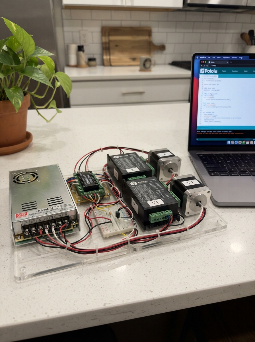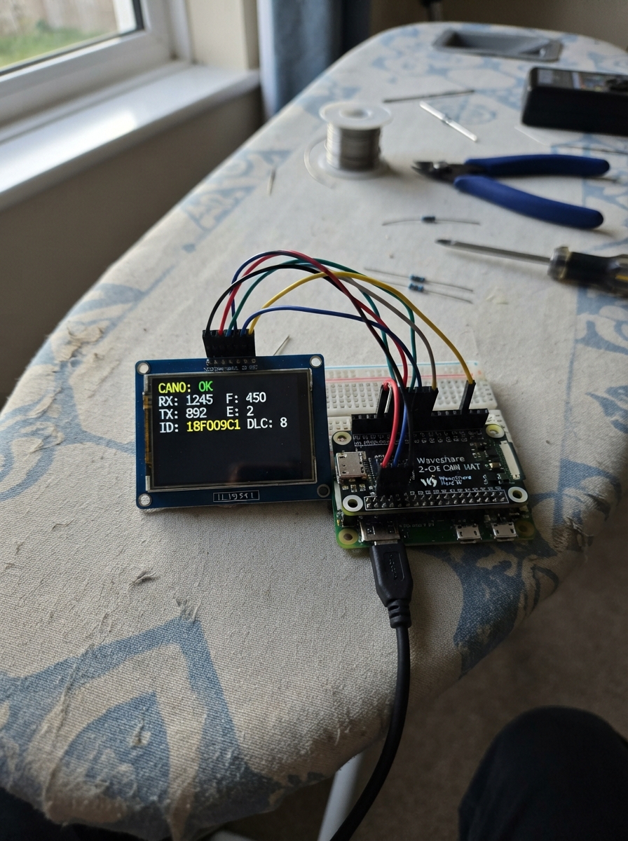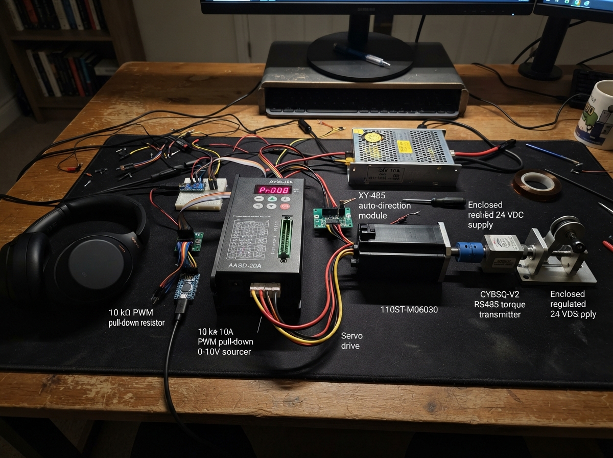
This project demonstrates how to build a torque-limited servo system using an ESP32 microcontroller to command a AASD-20A servo drive and 110ST-M06030 motor while monitoring real-time torque feedback from a CYBSQ-V2 RS485 transmitter. The system enforces safe operating limits by reading torque data over RS485 communication and reversing motor direction when thresholds are exceeded, making it suitable for applications requiring load protection or collision detection.
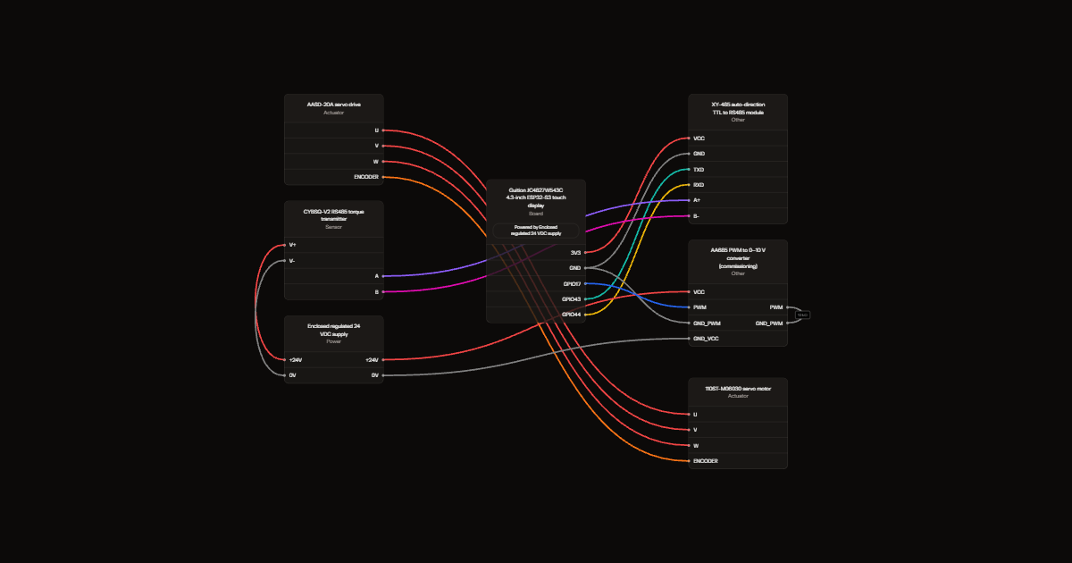
The guide provides a complete wiring diagram showing connections between the ESP32, XY-485 RS485 module, servo drive, torque sensor, and 24 VDC power supply, along with a full parts list, firmware code with touchscreen UI support, and step-by-step assembly instructions. Builders will learn how to configure RS485 communication, integrate torque feedback into motion control logic, and safely commission the system before operation.
Wiring diagram
Gather all the parts
Assemble it in 4 steps
1. แยกชุดทดสอบเซนเซอร์และปิดไฟก่อนต่อ
ใช้เฉพาะจอผ่าน USB ชุดเซนเซอร์ที่ผู้ผลิตต่อมากับ CYBSQ-V2 โมดูล XY-485 และแหล่งจ่าย 24V แบบปิดมิดชิด เก็บสายเซนเซอร์เข้าตัวแปลงตามโรงงาน ไม่แกะหรือต่อไฟเพิ่มเข้า E+/E- ผังส่วนมอเตอร์และ AA685 เป็นงานเดิม ไม่ต้องต่อในรอบนี้
- ถอดไฟไดรฟ์และ AA685 รวมถึงสาย PWM GPIO17 และสาย GND_PWM ออกจากจอระหว่างทดสอบเซนเซอร์
- โปรแกรมฟัง UART RX IO44 / TX IO43 โดยไม่ส่งไบต์ ไม่มี PWM และไม่เขียนค่าตัวแปลง
2. ต่อสายออกตัวแปลงตามสีบนฉลาก
แดง V+ ไป +24V ของแหล่งจ่าย ดำ V- ไป 0V เขียว A ไป A+ ของ XY-485 ขาว B ไป B- ของ XY-485 เหลืองเขียว SHIELD หุ้มปลายแยกไว้ไม่ต่อขั้วใด เซนเซอร์และสายภายในที่ผู้ผลิตต่อไว้แล้วไม่แสดงในผังนี้ ไม่ต้องถอดหรือต่อใหม่
- ฉลากยืนยันไฟเข้า 12/24V แต่ไม่ได้ยืนยันแรงดัน excitation หรือการสอบเทียบ ห้ามนำไฟ 24V ต่อเข้าจอ GPIO หรือ XY-485 VCC ในผังนี้
- ไม่ต่อสายชิลด์เข้าขั้ว Earthed ของ XY-485 จนกว่าจะยืนยันหน้าที่ขั้วและวิธีต่อจากเอกสาร ไม่ถือว่ามี isolation
3. ตรวจโมดูลก่อนต่อสายเข้าจอ
ปิดไฟตรวจความต่อเนื่องและการลัดวงจรด้วยมิเตอร์ ต่อ XY-485 VCC ไป 3V3 ของจอและ GND ไป GND จอเท่านั้น ตรวจระดับเอาต์พุต RXD ว่าเข้ากับ GPIO 3.3V ก่อนเชื่อม UART แล้วต่อ TXD ของ XY-485 ไป TX0 / IO43 (ข้อมูลส่งจากจอ) และ RXD ไป RX0 / IO44 (ข้อมูลรับเข้าจอ) ตรวจขั้วจริงตามตัวอักษร ไม่ยึดตำแหน่งจากการกลับด้านบอร์ด
- หากยังไม่ยืนยัน RXD และขั้วของจริง ให้เว้นสาย TX0/RX0 (IO43/44) ไว้ก่อน ห้ามใช้ 5V หรือ 24V เลี้ยง XY-485 ในผังนี้
- ขั้ว Earthed ไม่ใช่กราวด์สัญญาณที่ยืนยันแล้ว ผังนี้ยังไม่เพิ่มสายเชื่อม 0V ของตัวแปลงเข้าจอ หากเอกสารกำหนดให้ใช้กราวด์สัญญาณร่วมต้องตรวจระบบกราวด์ก่อน ไม่ใช้ชิลด์แทน
4. ทดสอบสื่อสารแบบอ่านอย่างเดียว
โปรแกรมฟังคงที่ 9600 โดยเก็บโหมด 8N1 หรือ 8E1 ที่บันทึกไว้เดิม ไม่มีการวนโหมดหรือเปิด UART ใหม่ระหว่างรัน ทดสอบ 30–60 วินาทีและบันทึกภาพจอที่มี RX Groups CRC และ S ทุก 10 วินาที จอแสดงกลุ่มข้อมูลล่าสุด 4 กลุ่มพร้อมเวลาซอฟต์แวร์ จำนวนไบต์ และ HEX สูงสุด 18 ไบต์ต่อกลุ่ม ไม่ใช่การเก็บไบต์ทั้งหมด ช่อง USB เดิมใช้ Deploy เท่านั้น ไม่ส่งบันทึกหรือรับคำสั่ง N/E เพราะ GPIO43/44 ใช้กับ RS485 และ GPIO19/20 ใช้กับจอสัมผัส หากต้องเปลี่ยนโหมดให้ขอแก้เฟิร์มแวร์ในแชต ไม่เปลี่ยนสายหรือแหล่งจ่ายจากสภาพล่าสุด ไม่ส่งคำขออ่าน CRC ตรงเป็นเพียงหลักฐานประกอบ ไม่ยืนยันโปรโตคอลหรือแรงบิด
- ฉลากระบุ Modbus RTU 9600 baud ที่อยู่ 01 แต่ยังไม่ยืนยัน parity/stop bits รีจิสเตอร์ ค่ามีเครื่องหมายและสเกล ห้ามใช้ผังรีจิสเตอร์ BSQ-DG-V2 เป็นข้อยืนยัน
- ไม่สั่ง tare และไม่ใช้คำสั่งมอเตอร์สอบเทียบ เริ่มวัดศูนย์โดยไม่มีแรงแล้วใช้แรงอ้างอิงต่ำทั้งสองทิศหลังอ่านข้อมูลได้จริง
- เวลาแบ่งเฟรมเป็นเวลาที่ซอฟต์แวร์อ่าน UART ไม่ใช่เครื่องวิเคราะห์สัญญาณ หากมีข้อมูลต่อเนื่องหรือเฟรมติดกันต้องใช้เครื่องมือวัดยืนยัน จอปรับไม่เกินสองครั้งต่อวินาที
- ไม่เพิ่มกราวด์หรือชิลด์ ไม่สลับสายขณะมีไฟ และไม่ถือว่าการไม่ส่ง UART ยืนยันสถานะตัวขับบัสของโมดูล ต้องตรวจโมดูลจริงแยกต่างหาก
Review all connections
1. Connections between "drive" and "ESP32"
2. Connections between "motor" and "ESP32"
3. Connections between "rs485" and "ESP32"
4. Connections between "psu24" and "ESP32"
5. Connections between "aa685" and "ESP32"
6. Connections between "pwm_pd" and "ESP32"
7. Connections between "v2" and "ESP32"
Deploy the firmware
#include <Arduino.h>
#include <U8g2lib.h>
#include <Arduino_GFX_Library.h>
#include <math.h>
#include <TAMC_GT911.h>
#include <Preferences.h>

constexpr int BACKLIGHT_PIN = 2;
constexpr int TOUCH_SDA = 19;
constexpr int TOUCH_SCL = 20;
constexpr int TOUCH_INT = 18;
constexpr int TOUCH_RST = 38;
constexpr uint16_t SCREEN_WIDTH = 800;
constexpr uint16_t SCREEN_HEIGHT = 480;
constexpr uint16_t BOX_WIDTH = 180;
constexpr uint16_t BOX_HEIGHT = 110;
constexpr uint16_t BOX_MARGIN = 18;
constexpr int LCD_DE = 40;
constexpr int LCD_VSYNC = 41;
constexpr int LCD_HSYNC = 39;
constexpr int LCD_PCLK = 42;
constexpr int LCD_R0 = 45;
constexpr int LCD_R1 = 48;
constexpr int LCD_R2 = 47;
constexpr int LCD_R3 = 21;
constexpr int LCD_R4 = 14;
constexpr int LCD_G0 = 5;
constexpr int LCD_G1 = 6;
constexpr int LCD_G2 = 7;
constexpr int LCD_G3 = 15;
constexpr int LCD_G4 = 16;
constexpr int LCD_G5 = 4;
constexpr int LCD_B0 = 8;
constexpr int LCD_B1 = 3;
constexpr int LCD_B2 = 46;
constexpr int LCD_B3 = 9;
constexpr int LCD_B4 = 1;

Arduino_ESP32RGBPanel *rgbPanel = new Arduino_ESP32RGBPanel(
  LCD_DE, LCD_VSYNC, LCD_HSYNC, LCD_PCLK,
  LCD_R0, LCD_R1, LCD_R2, LCD_R3, LCD_R4,
  LCD_G0, LCD_G1, LCD_G2, LCD_G3, LCD_G4, LCD_G5,
  LCD_B0, LCD_B1, LCD_B2, LCD_B3, LCD_B4,
  0, 8, 4, 8,
  0, 8, 4, 8,
  1, 16000000
);

Arduino_RGB_Display *display = new Arduino_RGB_Display(
  SCREEN_WIDTH, SCREEN_HEIGHT, rgbPanel, 0, false
);
Arduino_Canvas *gfx = new Arduino_Canvas(SCREEN_WIDTH, SCREEN_HEIGHT, display);


// Passive UART capture only. No bus.write(), requests, tare or motor control.
// Keep explicit RX44/TX43; never select default pins or GPIO17.
HardwareSerial bus(1);
const uint32_t formats[]={SERIAL_8N1,SERIAL_8E1};
const char *names[]={"8N1","8E1"};
Preferences settings;
uint32_t lastSummary=0;
uint8_t rx[4096];
uint32_t frameBytes=0;
size_t count=0;
bool overflow=false;
uint8_t mode=0;
uint32_t lastByte=0,firstByte=0,modeStart=0,lastDraw=0;
uint32_t rxBytes=0,frames=0,crcOK=0,overflows=0;
String status="LISTENING",frame="--",previous="";
String summary="Waiting for first 10s summary";
uint32_t summaryNumber=0;
String recent[4];
uint32_t recentNumber=0;
uint16_t crc16(const uint8_t *p,size_t n){
 uint16_t c=0xffff;
 while(n--){c^=*p++;for(int i=0;i<8;i++)c=(c&1)?(c>>1)^0xa001:c>>1;}
 return c;
}
uint32_t gapUs(){return mode==0?3646:4011;} // ceil(3.5 * 10/11 bits / 9600)
void finishFrame(bool boundary=false){
 if(!count)return;
 frames++;
 bool valid=!overflow&&!boundary&&count>=4&&crc16(rx,count)==0;
 if(valid)crcOK++;
 if(overflow)overflows++;
 status=boundary?"PARTIAL AT RESTART":overflow?"BUFFER OVERFLOW":valid?"CRC MATCH - NOT TORQUE":"CRC NOT MATCHED";
 frame="";
 for(size_t i=0;i<count&&i<18;i++){char b[4];snprintf(b,sizeof(b),"%02X ",rx[i]);frame+=b;}
 for(int i=3;i>0;i--)recent[i]=recent[i-1];
 recentNumber++;
 recent[0]="#"+String(recentNumber)+" t="+String(firstByte/1000)+"ms n="+String(frameBytes)+" "+(boundary?"PARTIAL":overflow?"OVERFLOW":valid?"CRC MATCH":"CRC ?")+" "+frame;
 count=0;frameBytes=0;overflow=false;
}
void startMode(){
 bus.begin(9600,formats[mode],44,43);
 modeStart=millis();rxBytes=frames=crcOK=overflows=0;
 status="LISTENING";frame="--";

}
void line(int y,const String &s,int size=2,uint16_t color=0xffff){
 gfx->setTextColor(color);gfx->setTextSize(size);gfx->setCursor(24,y);gfx->print(s);
}
void draw(){
 String freshness=rxBytes?(uint32_t(micros()-lastByte)>=2000000UL?"NO NEW BYTES >=2s":"RECENT BYTES"):"NO BYTES RECEIVED";
 String key=String(mode)+status+frame+String(rxBytes)+String(frames)+String(crcOK)+String(overflows)+freshness+summary;
 if(key==previous)return;previous=key;
 gfx->fillScreen(0x1083);
 line(24,"TORQUE SENSOR - LISTEN ONLY",3);
 line(78,"CYBSQ-V2 | 9600 "+String(names[mode])+" | FIXED MODE");
 line(110,"TX: 0 | RX bytes: "+String(rxBytes)+" | Groups: "+String(frames));
 line(153,status,2,crcOK?0x07e0:0xffe0);
 line(202,"CRC matches: "+String(crcOK)+" | Overflow: "+String(overflows));
 line(251,"Torque: -- N.m (not decoded)");
 line(287,freshness+" | Last HEX retained");
 for(int i=0;i<4;i++)line(325+i*24,recent[i].length()?recent[i]:"--",1);
 line(426,summary,2,0xffe0);
 line(455,"ON-SCREEN CAPTURE | USB LOG DISABLED",1,0xffe0);
 gfx->flush();display->flush();
}
void setup(){
 pinMode(BACKLIGHT_PIN,OUTPUT);digitalWrite(BACKLIGHT_PIN,HIGH);
 // USB CDC disabled: GPIO19/20 belong to touch. UART0 pins belong to RS485.
 // Do not initialize Serial or Serial0 on this wiring.
 if(!display->begin()||!gfx->begin(GFX_SKIP_OUTPUT_BEGIN)){
  digitalWrite(BACKLIGHT_PIN,LOW);while(true)delay(1000);
 }
 gfx->setTextWrap(false);
 bus.setRxBufferSize(4096);
 settings.begin("uart-test",false);
 mode=settings.getUChar("fixed",0);if(mode>1)mode=0;

 startMode();draw();lastDraw=millis();
}
void loop(){
 while(bus.available()){
  uint32_t t=micros();
  if(count&&uint32_t(t-lastByte)>=gapUs())finishFrame();
  int b=bus.read();if(b<0)break;
  if(!count)firstByte=t;
  rxBytes++;frameBytes++;if(count<sizeof(rx))rx[count++]=uint8_t(b);else overflow=true;
  lastByte=t;
 }
 if(count&&uint32_t(micros()-lastByte)>=gapUs())finishFrame();
 uint32_t now=millis();
 if(uint32_t(now-lastSummary)>=10000){
  lastSummary=now;
  summaryNumber++;
  summary="S"+String(summaryNumber)+" t="+String(now/1000)+"s RX="+String(rxBytes)+" F="+String(frames)+" CRC="+String(crcOK);

 }
 // Draw only changed content, at most twice per second and outside a frame.
 if(!count&&!bus.available()&&uint32_t(now-lastDraw)>=500){draw();lastDraw=now;}
 delayMicroseconds(100);
}
Download project files
Remix this project
Make it yours in one click
Open a full copy of this project in your own Schematik workspace, diagram, code, parts, and assembly steps included. Swap the sensor, add features, or redesign the whole thing with AI. The author's original stays untouched.