Community project
Wanted To Put Assistant That Shows How Dry
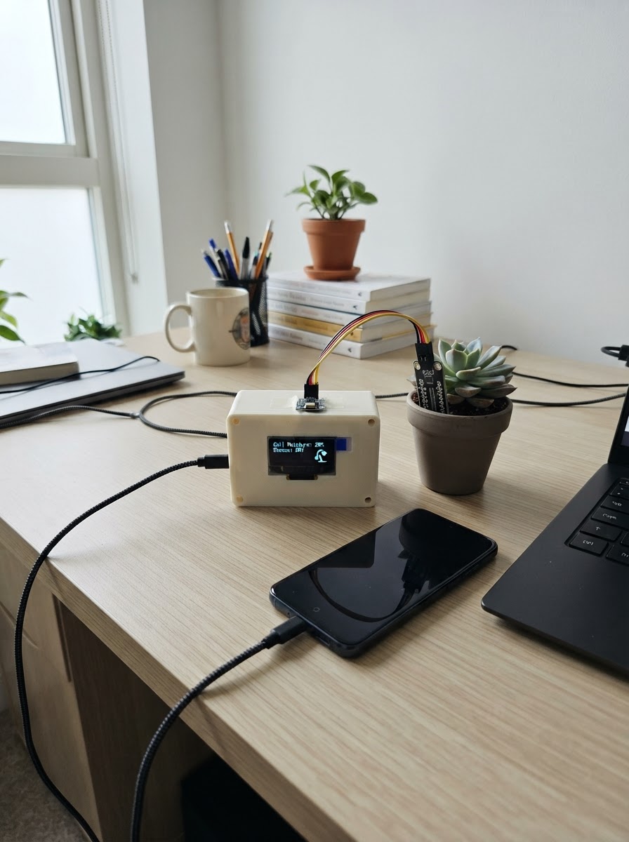
This project builds a plant monitoring system that tracks soil moisture and light levels to help keep plants healthy. The Arduino Uno reads data from a capacitive soil moisture sensor and a BH1750 light sensor, then reports conditions via serial output with helpful labels like "DRY - water soon" and "direct sun."
The guide includes a complete wiring diagram, parts list, and pre-written firmware ready to upload. Assembly takes just a few minutes: connect the soil sensor to analog input, wire the light sensor via I2C, then power up to start monitoring. Calibration values are included to get accurate moisture readings right away.
Wiring diagram

Gather all the parts
Assemble it in 4 steps
1. Keep the Arduino unpowered while wiring
Place the Arduino Uno, the SEN0308 capacitive soil sensor, and the BH1750 light-sensor module on your work surface. Disconnect the Uno USB cable before attaching or moving any wires.
- Use female-to-female jumper wires if your sensor modules have header pins.
- The Arduino Uno will be powered by its USB port after all connections are checked.
- Do not insert the soil probe into water while it is powered unless the specific sensor module is rated for that use.
- Avoid shorting the Uno 5V pin to GND.
2. Wire the capacitive soil sensor
Connect soil_sensor VCC (usually the red lead) to the Uno 5V pin. Connect soil_sensor GND (usually black) to an Uno GND pin. Connect soil_sensor AOUT / Signal (usually yellow) to Uno A0. Its output is at most 2.9 V, so it is safe for the Uno A0 analogue input.
- Insert only the flat sensing end into soil; keep the electronics/connector above the soil line.
- Route the sensor cable away from the USB connector if possible.
- Check the labels on the actual module; wire by labels, not wire colour alone.
- Never connect the sensor signal pin directly to 5V.
3. Wire the BH1750 light sensor
Connect light_sensor VCC to Uno 5V and light_sensor GND to Uno GND. Connect light_sensor SDA to Uno A4 (SDA), and light_sensor SCL to Uno A5 (SCL). Connect light_sensor ADDR to GND; this selects the firmware’s expected I2C address, 0x23.
- Many BH1750 breakout boards mark the pins as VCC, GND, SCL, SDA, and ADDR.
- Place the light sensor where it sees the same light as the plant, without being shaded by the Uno or leaves.
- Do not swap SDA and SCL.
- Do not leave ADDR connected to 5V: that would select address 0x5C while this firmware uses 0x23.
4. Inspect and power the monitor
Check every connection against the labels: soil_sensor uses 5V, GND, and A0; light_sensor uses 5V, GND, A4/SDA, A5/SCL, and ADDR-to-GND. Once checked, plug the Uno into USB. Use Schematik’s Deploy button to put the firmware on the board; readings are sent at 9600 baud every five seconds.
- For the first moisture calibration, note the raw reading in dry soil/sand and in fully wet soil, then update the two calibration constants in the project if needed.
- The reported percentage is a relative soil moisture estimate, not a laboratory measurement.
- USB should be the only power source for this low-current project; do not add a second power supply while USB is connected.
Review all connections
1. Connections between "soil_sensor" and "Arduino"
2. Connections between "light_sensor" and "Arduino"
Deploy the firmware
#include <Arduino.h>
#include <Wire.h>
#include <BH1750.h>


// Forward declarations
int moisturePercentFromRaw(int rawValue);
void printReport();

const uint8_t SOIL_PIN = A0;
const int SOIL_WET_RAW = 500;   // Starting calibration: sensor in saturated soil/water
const int SOIL_DRY_RAW = 820;   // Starting calibration: sensor in dry soil/sand
const unsigned long REPORT_INTERVAL_MS = 5000UL;

BH1750 lightMeter;
bool lightSensorReady = false;
unsigned long lastReportMs = 0;

int moisturePercentFromRaw(int rawValue) {
  long percent = map(rawValue, SOIL_DRY_RAW, SOIL_WET_RAW, 0, 100);
  return constrain(percent, 0, 100);
}

const char *moistureLabel(int percent) {
  if (percent <= 20) return "DRY - water soon";
  if (percent <= 50) return "MODERATE";
  if (percent <= 75) return "MOIST";
  return "WET";
}

const char *lightLabel(float lux) {
  if (lux < 100.0f) return "low light";
  if (lux < 1000.0f) return "indoor/overcast light";
  if (lux < 10000.0f) return "bright shade";
  return "direct sun";
}

void printReport() {
  int soilRaw = analogRead(SOIL_PIN);
  int moisturePercent = moisturePercentFromRaw(soilRaw);

  Serial.println(F("--- Plant conditions ---"));
  Serial.print(F("Soil raw reading: "));
  Serial.println(soilRaw);
  Serial.print(F("Soil moisture: "));
  Serial.print(moisturePercent);
  Serial.print(F("% - "));
  Serial.println(moistureLabel(moisturePercent));

  if (lightSensorReady) {
    float lux = lightMeter.readLightLevel();
    if (lux >= 0.0f) {
      Serial.print(F("Light: "));
      Serial.print(lux, 1);
      Serial.print(F(" lux - "));
      Serial.println(lightLabel(lux));
    } else {
      Serial.println(F("Light: BH1750 read failed; check its SDA/SCL wiring."));
    }
  } else {
    Serial.println(F("Light: BH1750 not detected; check power and I2C wiring."));
  }
  Serial.println();
}

void setup() {
  Serial.begin(9600);
  Wire.begin();
  lightSensorReady = lightMeter.begin(BH1750::CONTINUOUS_HIGH_RES_MODE, 0x23, &Wire);

  Serial.println(F("Plant soil and sunlight monitor started."));
  Serial.println(F("Readings are printed every 5 seconds."));
  if (!lightSensorReady) {
    Serial.println(F("Warning: BH1750 was not found at I2C address 0x23."));
  }
}

void loop() {
  unsigned long now = millis();
  if (now - lastReportMs >= REPORT_INTERVAL_MS) {
    lastReportMs = now;
    printReport();
  }
}
Remix this project
Make it yours in one click
Open a full copy of this project in your own Schematik workspace — diagram, code, parts, and assembly steps included. Swap the sensor, add features, or redesign the whole thing with AI. The author's original stays untouched.
Related projects
Necesito Hacer Un Circuito De Un Oxiometro Con
Arduino · September 25, 2026MARIA PAULA LAMBOGLIA VARGAS
Laser Harp Instrument
Arduino · September 25, 2026juliasualoka2
Três Sensores de Luz
Arduino · September 25, 2026arthur.brazil