Community project
Wiadomości Dla Mamy
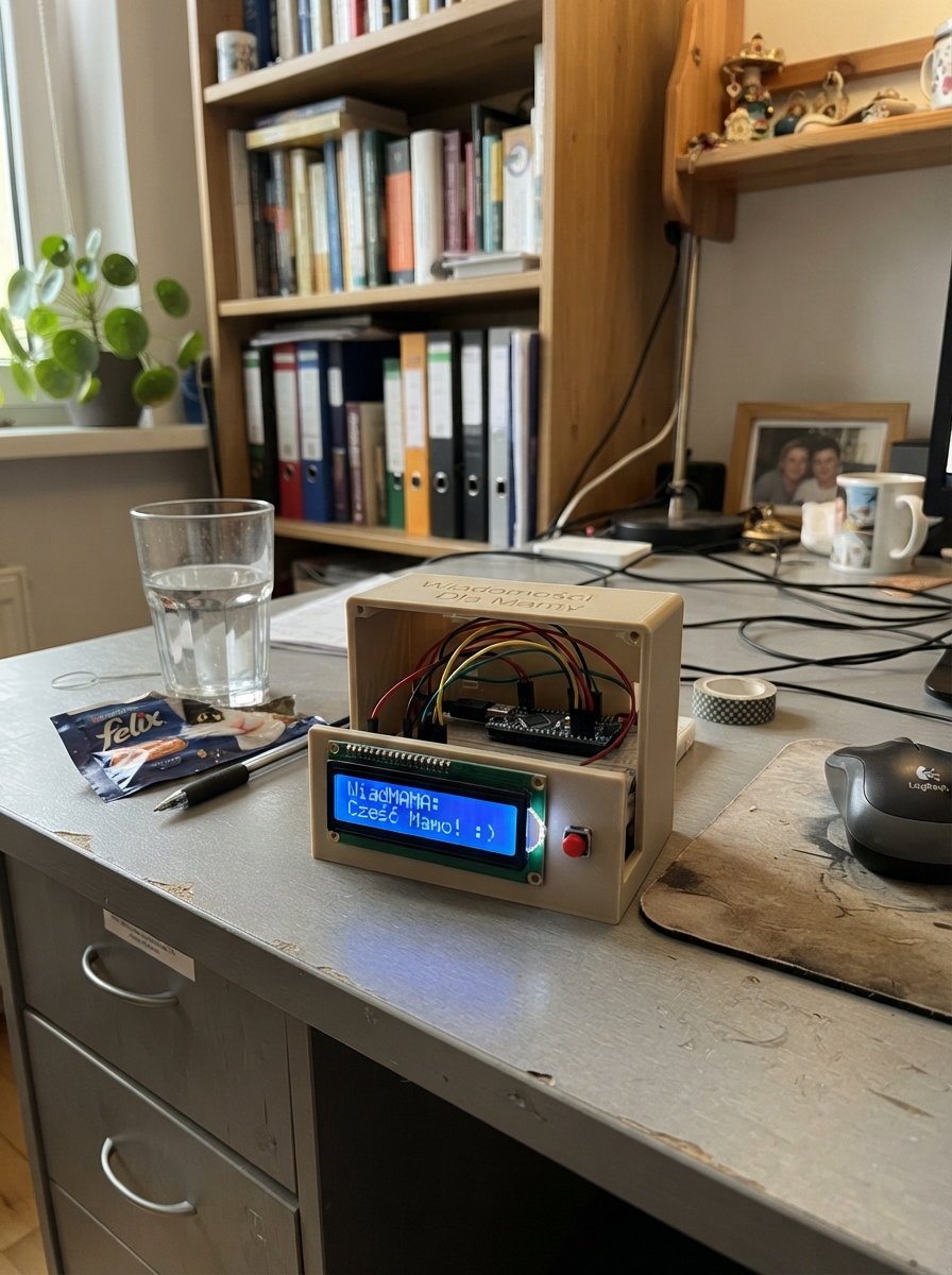
Wiadomości Dla Mamy is a status display system built around an Arduino Uno that lets users communicate their current state with a simple button press. Four push buttons trigger different messages on a 16x2 LCD screen, each conveying a distinct status—from "occupied" to "available" to mood indicators—making it easy to share information without typing or speaking.
This guide provides a complete wiring diagram showing how to connect the four push buttons and I2C LCD display to the Arduino Uno, a full parts list, the complete firmware with debounce logic, and step-by-step assembly instructions. Builders will have everything needed to assemble and program a working status communicator.
Wiring diagram

Gather all the parts
Assemble it in 6 steps
1. Odłącz Arduino od USB
Najpierw wyjmij przewód USB z Arduino Uno. Dzięki temu przypadkowe zetknięcie kabelków podczas zmian nie uszkodzi płytki ani ekranu.
- Nie przekładaj przewodów, gdy Arduino jest zasilane przez USB.
2. Zostaw ekran LCD podłączony
Ekran pozostaje podłączony tak jak wcześniej: VCC → 5V (zasilanie), GND → GND (powrót prądu), SDA → A4 (dane), SCL → A5 (zegar danych).
- Upewnij się, że VCC i GND nie są zamienione — zamienione zasilanie może uszkodzić ekran.
3. Podłącz pierwszy i drugi przycisk
Pierwszy przycisk zostaw między D2 (sygnał) a GND (powrót prądu) — wybiera „ZAJETY / Wyjdz z pokoju”. Drugi zostaw między D3 (sygnał) a GND (powrót prądu) — wybiera „WOLNY / Mozna wejsc”.
- W typowym małym przycisku wybierz nóżki po przeciwnych stronach, a nie dwie nóżki obok siebie.
4. Podłącz trzeci przycisk
Trzeci przycisk podłącz jedną stroną do D4 (sygnał), a nóżką po przeciwnej stronie do GND (powrót prądu). Ten przycisk pokaże „NORMALNY / Rob co chcesz”.
- Jeżeli przycisk jest w płytce stykowej, włóż go przez środkową szczelinę płytki.
5. Podłącz czwarty przycisk
Czwarty przycisk podłącz jedną stroną do D5 (sygnał), a nóżką po przeciwnej stronie do GND (powrót prądu). Ten przycisk pokaże „ZLY / WYJAZD!”.
- Nie podłączaj żadnego z czterech przycisków do 5V — każdy ma zwierać tylko swój pin D2, D3, D4 lub D5 z GND.
6. Podłącz zasilanie
Sprawdź, czy każdy przycisk ma jeden przewód do swojego pinu, a drugi do GND. Podłącz Arduino Uno do komputera przewodem USB.
Review all connections
1. Connections between "lcd_1" and "Arduino"
2. Connections between "button_1" and "Arduino"
3. Connections between "button_2" and "Arduino"
4. Connections between "button_3" and "Arduino"
5. Connections between "button_4" and "Arduino"
Deploy the firmware
#include <Arduino.h>
#include <Wire.h>
#include <LiquidCrystal_I2C.h>

const uint8_t BUTTON_1_PIN = 2;
const uint8_t BUTTON_2_PIN = 3;
const uint8_t BUTTON_3_PIN = 4;
const uint8_t BUTTON_4_PIN = 5;
const unsigned long DEBOUNCE_MS = 35;

LiquidCrystal_I2C lcd(0x27, 16, 2);

struct Button {
  uint8_t pin;
  bool lastReading;
  bool stableState;
  unsigned long changedAt;
  const char *line1;
  const char *line2;
};

Button buttons[] = {
  {BUTTON_1_PIN, HIGH, HIGH, 0, "ZAJETY", "Wyjdz z pokoju"},
  {BUTTON_2_PIN, HIGH, HIGH, 0, "WOLNY", "Mozna wejsc"},
  {BUTTON_3_PIN, HIGH, HIGH, 0, "NORMALNY", "Rob co chcesz"},
  {BUTTON_4_PIN, HIGH, HIGH, 0, "ZLY", "WYJAZD!"}
};

const uint8_t BUTTON_COUNT = sizeof(buttons) / sizeof(buttons[0]);

void showMessage(const char *line1, const char *line2) {
  lcd.clear();
  lcd.setCursor(0, 0);
  lcd.print(line1);
  lcd.setCursor(0, 1);
  lcd.print(line2);
}

void setup() {
  for (uint8_t i = 0; i < BUTTON_COUNT; i++) {
    pinMode(buttons[i].pin, INPUT_PULLUP);
  }

  lcd.init();
  lcd.backlight();
  showMessage("Wybierz status", "Nacisnij guzik");
}

void loop() {
  const unsigned long now = millis();

  for (uint8_t i = 0; i < BUTTON_COUNT; i++) {
    Button &button = buttons[i];
    const bool reading = digitalRead(button.pin);

    if (reading != button.lastReading) {
      button.changedAt = now;
      button.lastReading = reading;
    }

    if ((now - button.changedAt) >= DEBOUNCE_MS && reading != button.stableState) {
      button.stableState = reading;
      if (button.stableState == LOW) {
        showMessage(button.line1, button.line2);
      }
    }
  }
}
Remix this project
Make it yours in one click
Open a full copy of this project in your own Schematik workspace — diagram, code, parts, and assembly steps included. Swap the sensor, add features, or redesign the whole thing with AI. The author's original stays untouched.