On this page
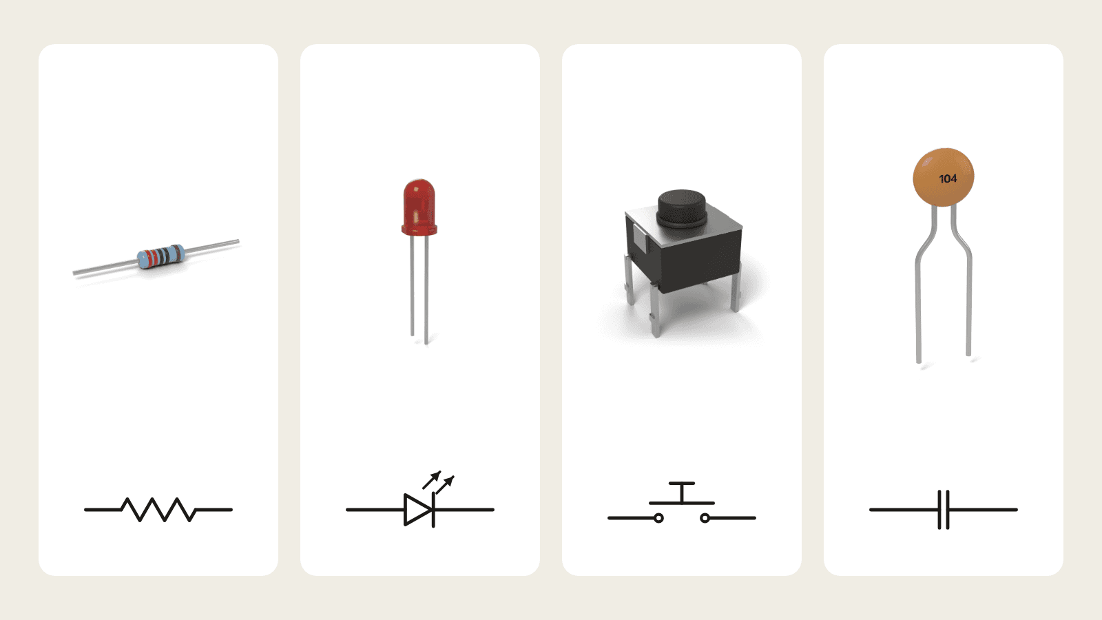
You tip a parts bag onto the desk and out roll a striped tube, a red dome with uneven legs and a little black block with 3 pins. Each one has a name, a job and a drawing that stands for it on a schematic, the wiring map for a circuit. Here they are side by side.
Each part below shows what it looks like and its circuit symbol. The letter after the name is its label on a schematic: R1 is the first resistor, R2 the second. Which way around tells you if the part has a + and a − side. Get those right before you power up.
Parts that control current
Resistor (R)
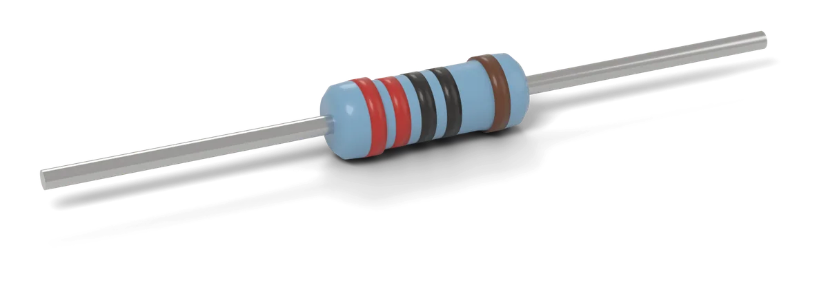
Limits how much current flows. It's the part that keeps a light-emitting diode (LED) from burning out.
- In the Starter Kit: 3 values: 220Ω, 1kΩ and 10kΩ
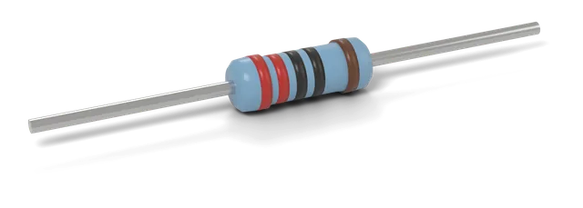
- Spot it: A small tube with colored bands and a wire out of each end. The bands tell you its value in ohms (Ω).
- Read the symbol: A zigzag in US-style drawings or a plain box in IEC-style drawings. Both mean the same part. The value is written next to it, like 220Ω.
- Which way around: Either way around. Resistors don't care which end goes where.
Potentiometer (RV)
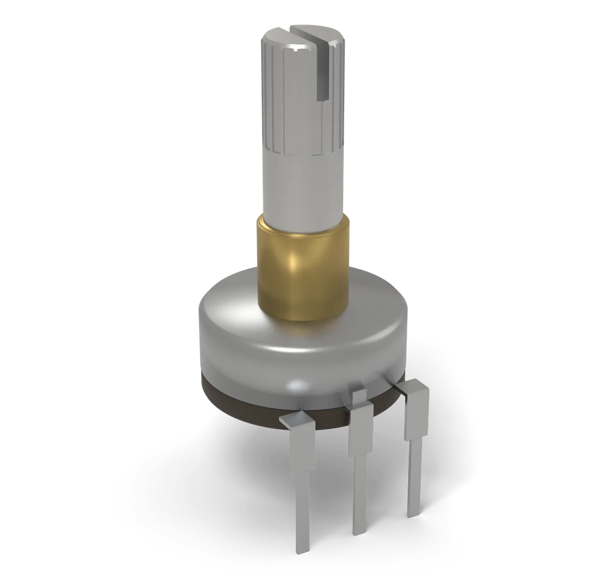
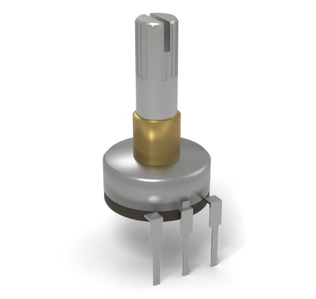
A resistor you adjust with a knob. Wire the middle leg to an analog pin, one that reads a voltage instead of only on or off, and your code can read the knob's position.
- In the Starter Kit: 1 at 10kΩ
- Spot it: A shaft on top and 3 legs underneath. The value, like B10K, is printed on the body. B means the resistance changes evenly as you turn it, and 10K is 10kΩ.
- Read the symbol: A resistor with an arrow pointing at it. The arrow is the middle leg, the wiper that slides along the track.
- Which way around: Outer legs go to 3V3 (the board's 3.3V pin) and GND (ground, 0V), middle leg to an analog pin. Swap the 2 outer legs to flip which way you turn it to raise the voltage.
Photoresistor (R)
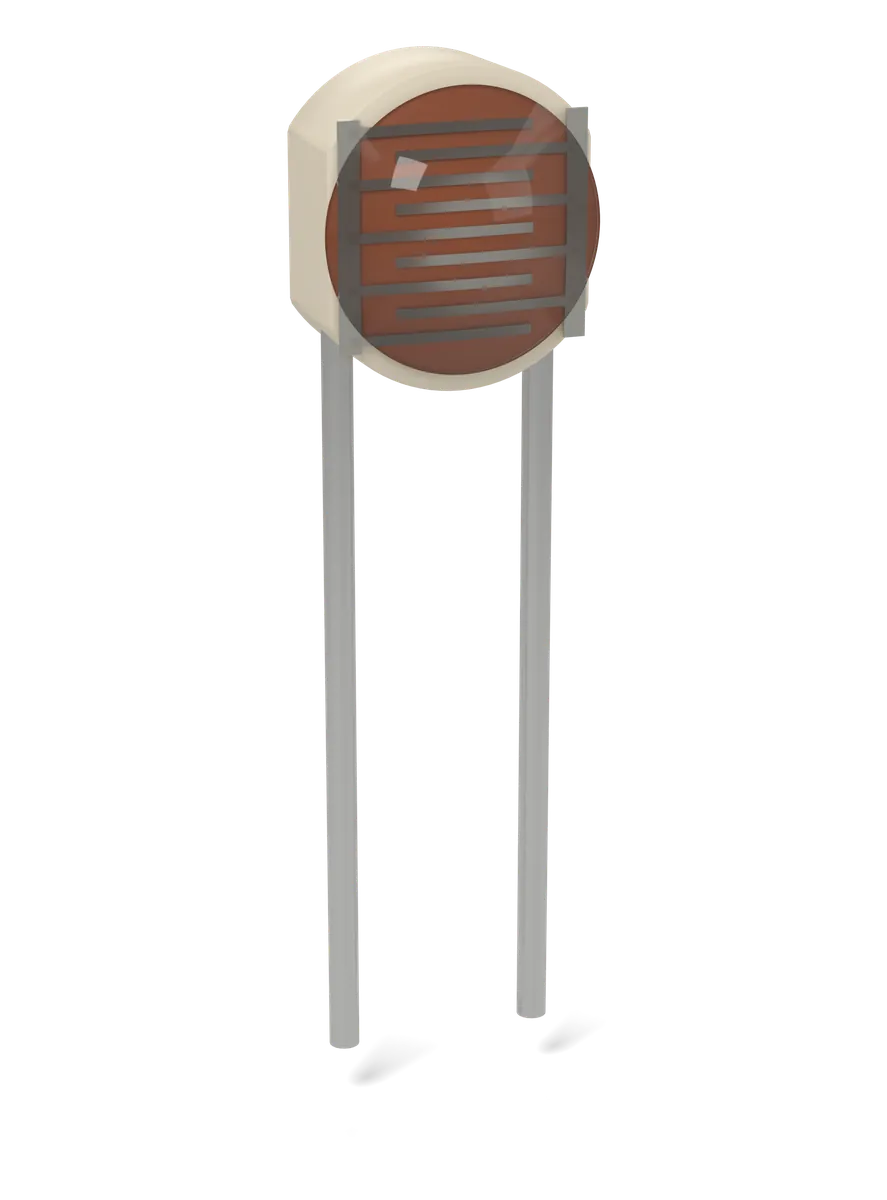
Changes its resistance with light. Bright light lowers it, darkness raises it.
- In the Starter Kit: on the light sensor module
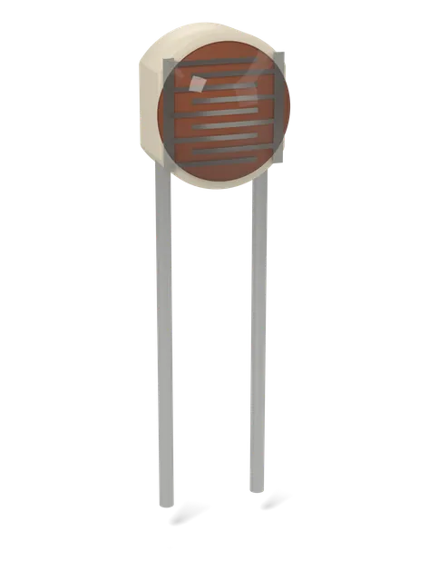
- Spot it: A small disc with a wiggly orange line across its face and 2 legs. Often called an LDR, short for light-dependent resistor.
- Read the symbol: A resistor with 2 arrows pointing in. Arrows pointing in mean light goes into the part.
- Which way around: Either way around.
Parts that store or supply energy
Ceramic capacitor (C)
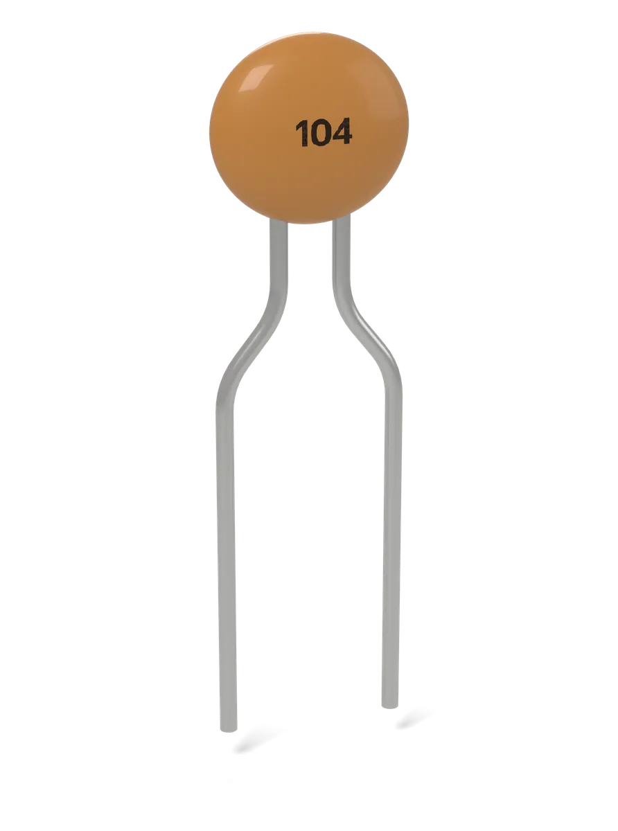
Stores a tiny bit of charge and lets it go fast. It smooths little dips in the power next to a chip.
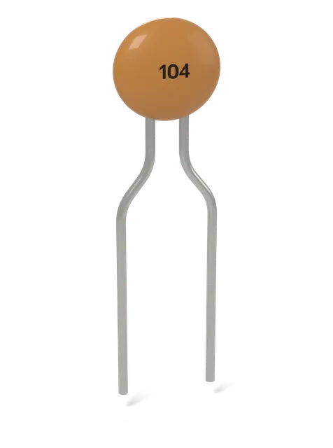
- Spot it: A small orange or blue blob with 2 legs and a 3-digit code. 104 means 10 with 4 zeros in picofarads: 100nF.
- Read the symbol: 2 straight parallel lines, like 2 plates with a gap between them. Older US drawings curve 1 plate.
- Which way around: Either way around.
Electrolytic capacitor (C)
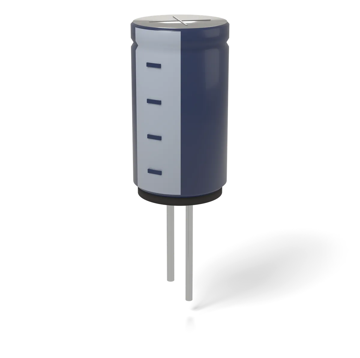
Usually has far more capacitance than a ceramic capacitor, so it can store more charge. It keeps a supply steady when a motor or speaker suddenly pulls current.
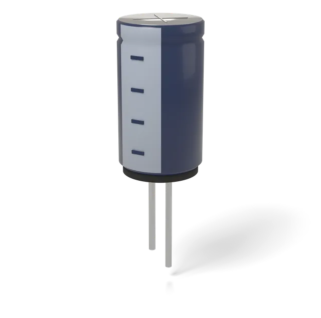
- Spot it: A little can with a light stripe down one side. The stripe has minus signs on it.
- Read the symbol: 2 plates with a + by one of them. That plate is the + leg. US drawings often curve the other plate, but some curve a plate on every capacitor, so look for the +.
- Which way around: This one has a + and a −. The stripe marks the − leg, and on a new part the longer leg is +. Do not fit it backward. It can bulge or pop.
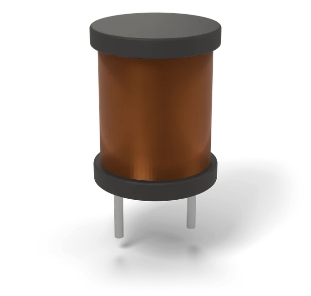
Inductor (L)
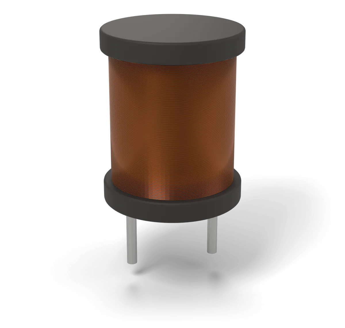
A coil of wire that stores energy in a magnetic field. It resists sudden changes in current, so power circuits use it to smooth things out.
- Spot it: Copper wire wound around a core. Some look like fat resistors with bands.
- Read the symbol: A row of bumps, like a coil seen from the side.
- Which way around: Either way around.
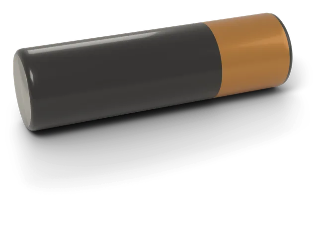
Battery (BT)
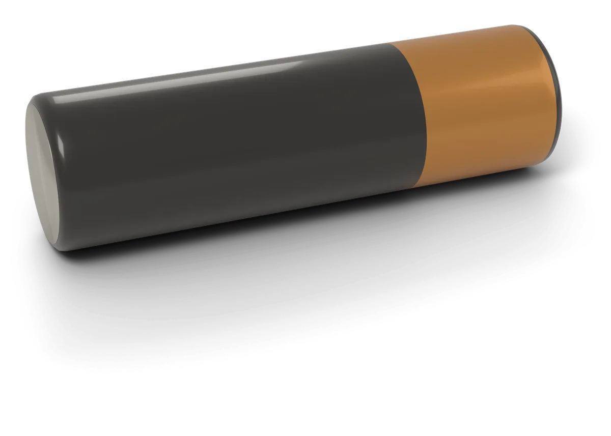
Supplies power when you're away from a USB cable.
- Spot it: Its voltage is printed on it, along with + and −.
- Read the symbol: A long thin line and a short thick line. The long line is +. More pairs drawn in a row mean more cells.
- Which way around: + and − matter. Do not plug it in backward. It can damage your board.
Parts that let current through one way
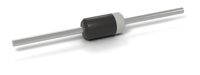
Diode (D)
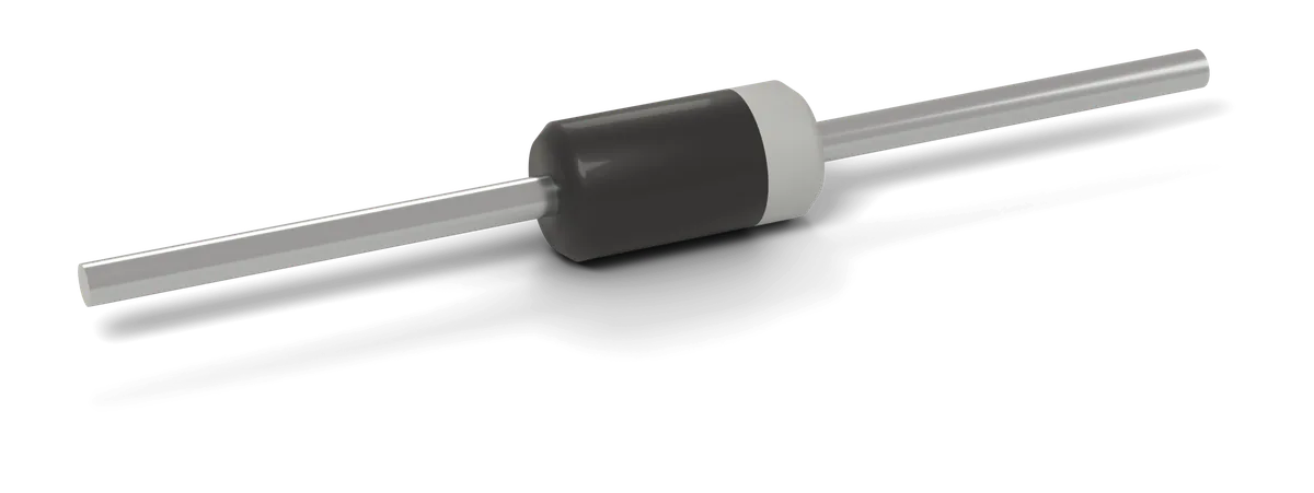
Lets current flow one way only. Wired in line with the power, it can stop a backward battery from frying your board.
- Spot it: A small black tube with 1 silver or white band near an end.
- Read the symbol: A triangle pointing at a bar. Current flows the way the triangle points. The bar is the cathode (K).
- Which way around: The band on the body is the bar in the symbol: the cathode.
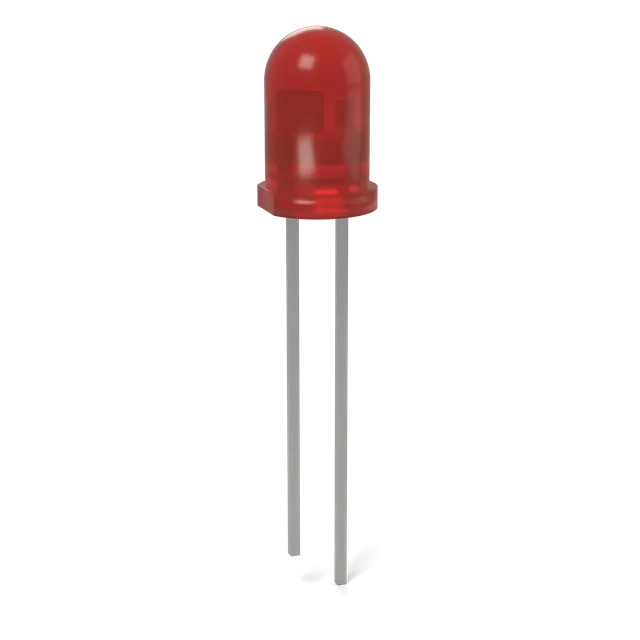
LED (D)
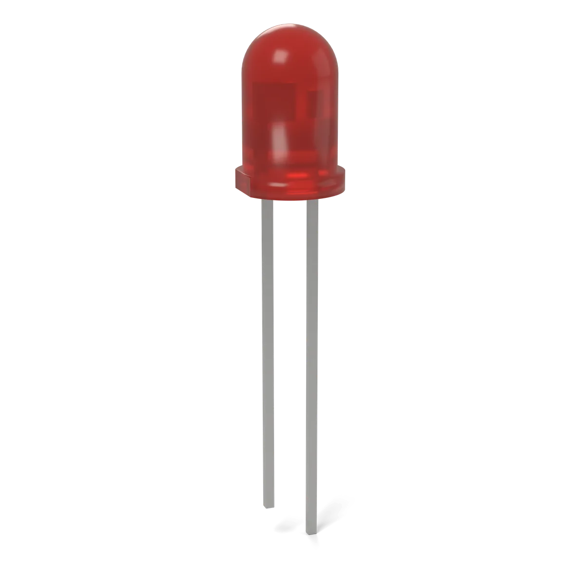
A diode that glows. It needs a resistor in line so the current stays safe.
- In the Starter Kit: red, yellow and green
- Spot it: A colored dome with 1 long leg and 1 short leg, until the legs are trimmed.
- Read the symbol: A diode with 2 arrows pointing out. Arrows pointing out mean light comes out.
- Which way around: Long leg is the anode (+). Short leg, by the flat edge of the rim, is the cathode (−). In the circuit below, the long leg faces the resistor and the short leg goes to GND.
Parts that switch things on and off
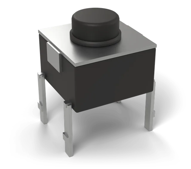
Push button (SW)
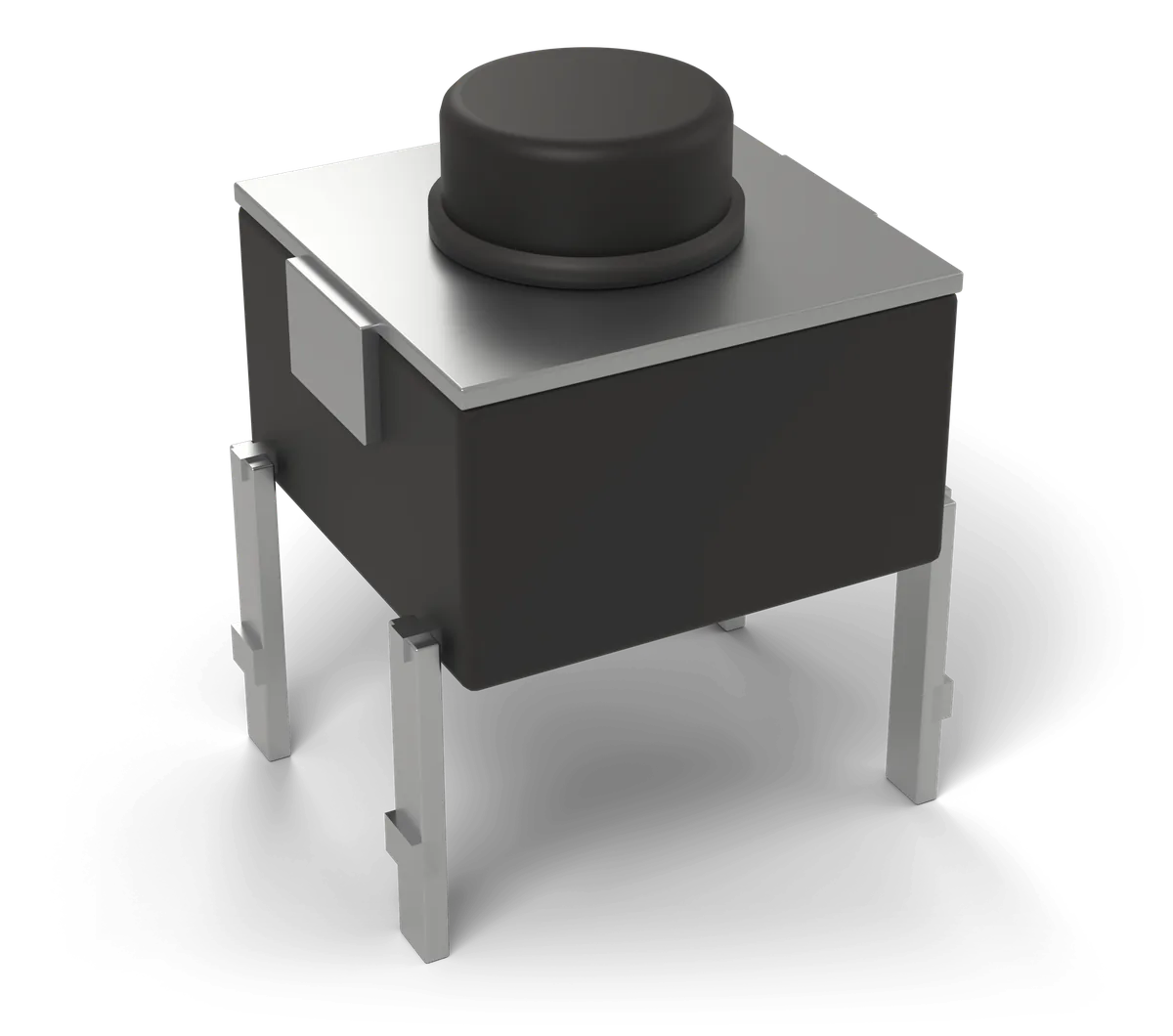
Connects 2 points while you hold it down. Your code reads it as a press.
- In the Starter Kit: included
- Spot it: A square with a round button on top and 4 legs.
- Read the symbol: A bar sitting above 2 contacts, with a little plunger on top. Push the plunger and the bar closes the gap.
- Which way around: 4 legs, 2 pairs. Each pair is joined inside the switch. Wire across the switch, corner to corner, if you're unsure.
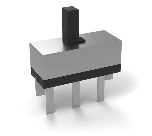
Slide switch (SW)
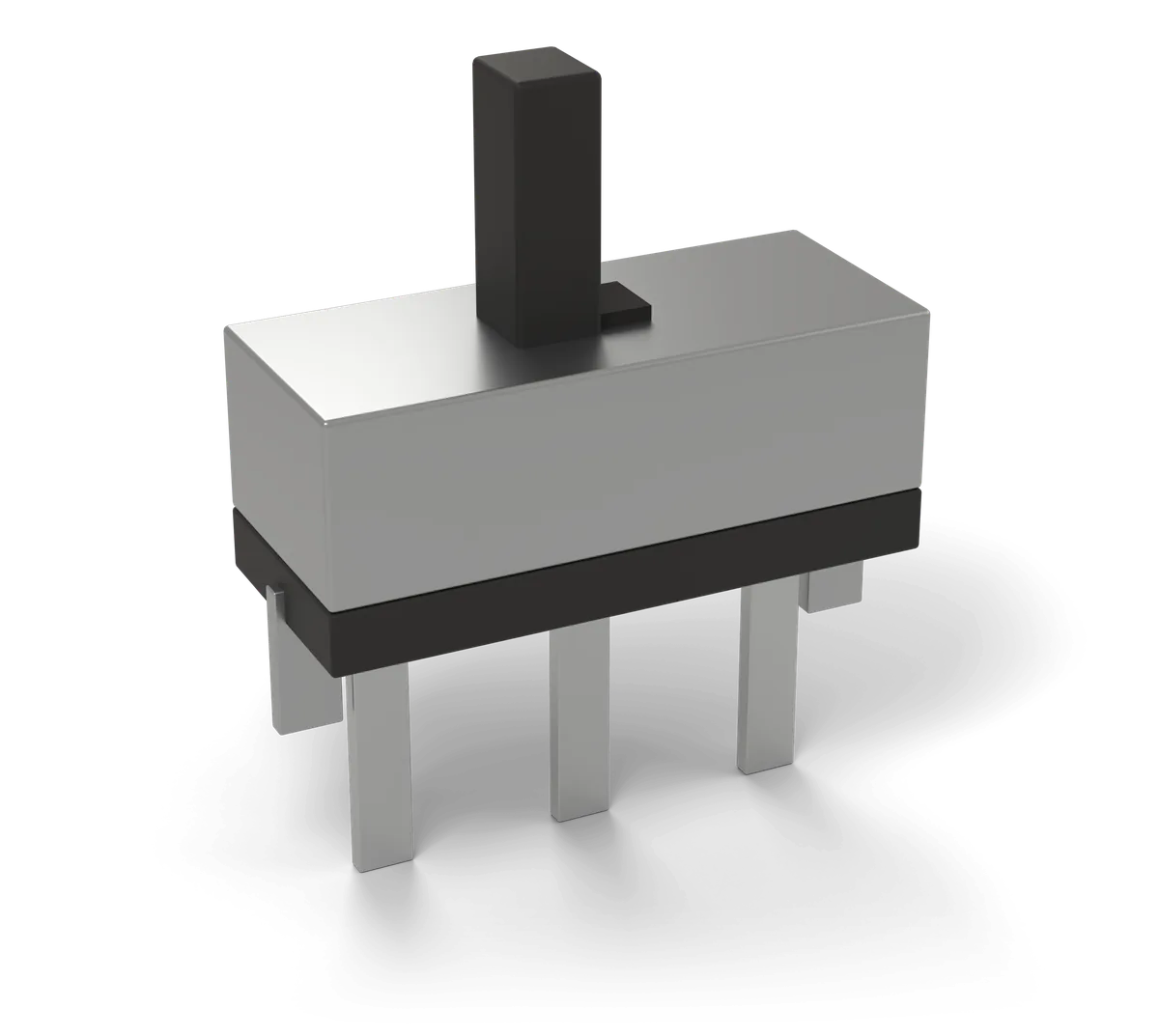
Stays in either position. For an on/off power switch, use the middle leg and 1 outer leg, and leave the other outer leg unconnected.
- Spot it: A small metal box with a sliding tab and 3 legs.
- Read the symbol: A lever that joins the common contact to one of 2 others.
- Which way around: The middle leg is common. It connects to the left leg or the right leg, depending on the slider.
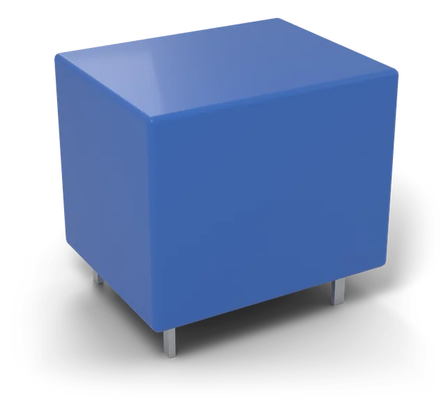
Relay (K)
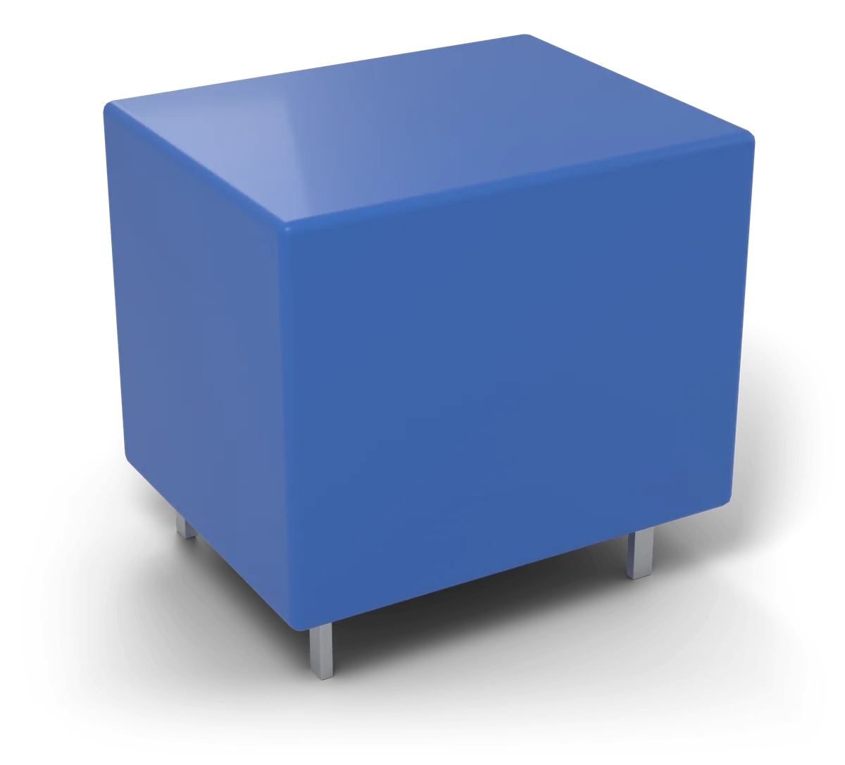
A switch flipped by an electromagnet. A small current in the coil switches a separate, bigger circuit. Do not switch wall power with a relay on a breadboard. Mains voltage can kill, and a breadboard is not built to carry it.
- Spot it: A plastic box, often blue, with its coil voltage printed on top.
- Read the symbol: A coil (a box) linked by a dashed line to a switch. The dashed line means they move together. The switch rests on NC. When the coil turns on, it moves over to NO. COM is common, NC is normally closed and NO is normally open. Normally means with the coil off.
- Which way around: Coil pins and switch pins are separate circuits. Do not drive a bare relay coil from a board pin. It needs more current than the pin gives and kicks back a voltage spike when it turns off. A relay module adds the driver parts, so check that its input works with your board.
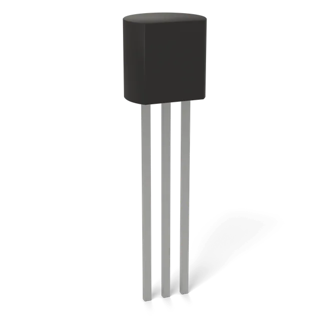
NPN transistor (Q)
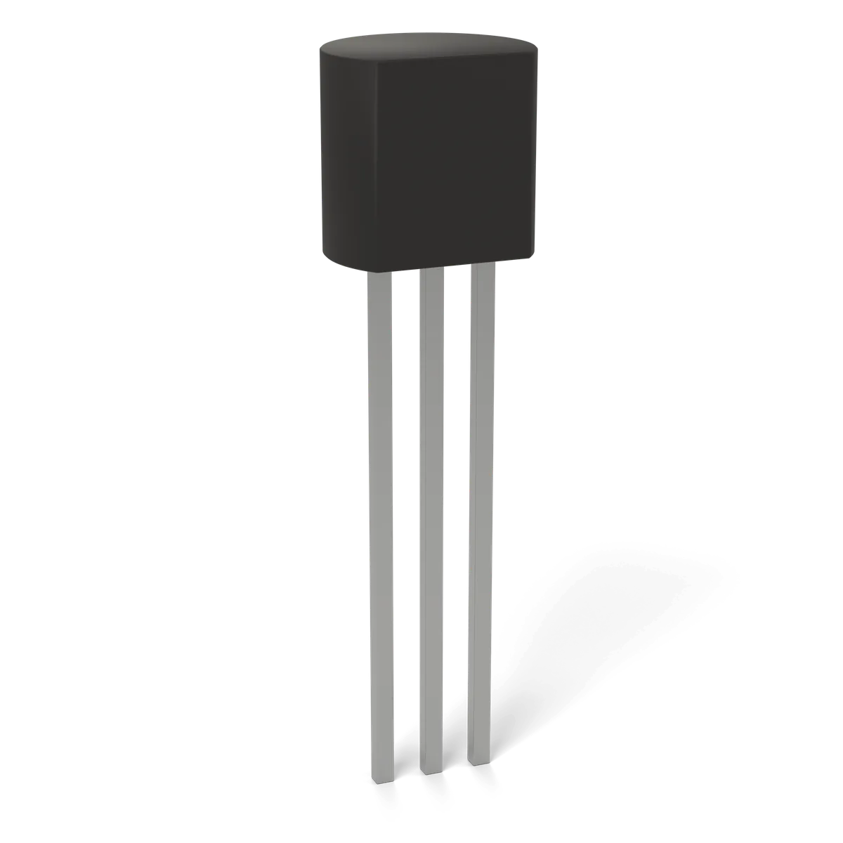
A small current into the base switches a bigger current between collector and emitter. A pin can switch a load it can't power on its own. Do not wire a board pin straight to the base. Put a resistor in between, around 1kΩ, or the pin can be damaged by too much current.
- Spot it: A small black half-cylinder with a flat face, 3 legs and a part number like PN2222A.
- Read the symbol: A line for the base with 2 diagonal legs. The arrow sits on the emitter and points out on an NPN.
- Which way around: The order of B, C and E changes between part numbers. Check the datasheet for your exact part.
N-channel MOSFET (Q)
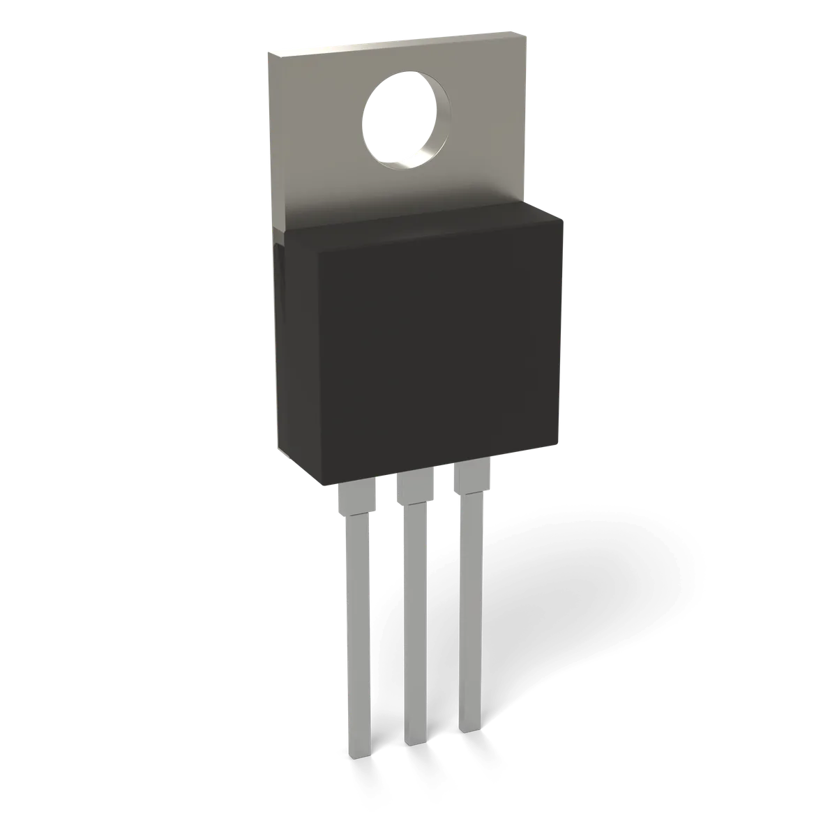
A switch for big loads like LED strips and motors. Voltage between gate and source turns it on. Do not switch a motor without a diode across it. When it turns off, it kicks back a voltage spike that can damage the MOSFET.
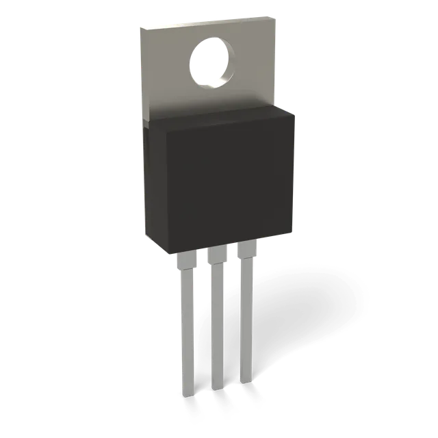
- Spot it: Often a black block with a metal tab and a hole, 3 legs and a part number like IRLZ44N.
- Read the symbol: A gate line that doesn't touch the channel, and an arrow pointing in on an N-channel part.
- Which way around: Gate, drain, source. The order depends on the part, so check the datasheet. To switch it from a 3.3V board pin, pick one whose datasheet gives its on-resistance, the resistance between drain and source when it's on, at a gate voltage of 3.3V or lower. The IRLZ44N gives it at 4V and up, so it may not turn fully on from 3.3V.
Parts that make sound
Buzzer (BZ)
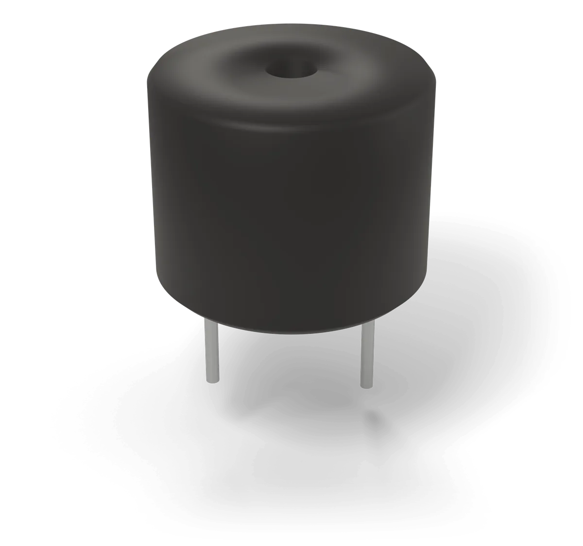
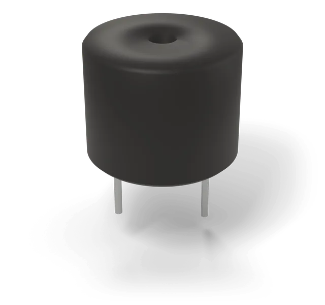
Beeps. An active buzzer beeps on its own. A passive one plays the tone your code sends.
- In the Starter Kit: 1 active and 1 passive
- Spot it: A small black cylinder with a hole on top and 2 legs. Many have a + on the label.
- Read the symbol: A square with a short line slanting off one corner.
- Which way around: Many buzzers mark a + leg, usually the longer one.
Chips and the parts around them
Voltage regulator (U)
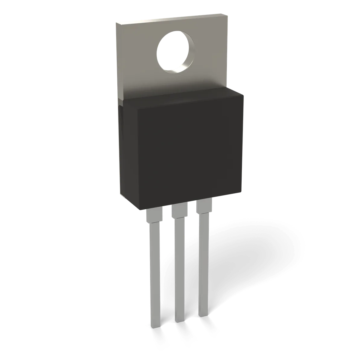
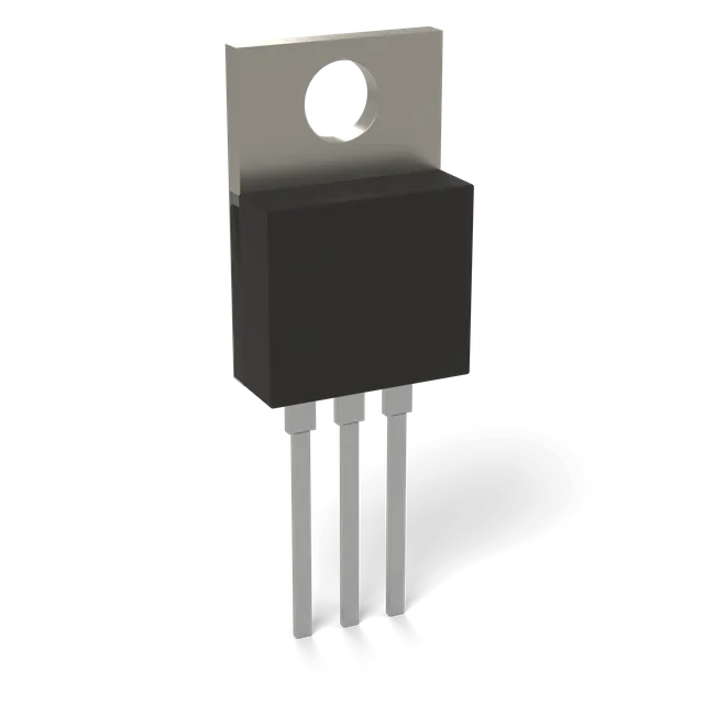
Turns a higher voltage into a steady lower one. The one shown here is a linear regulator. Your ESP32 board has one that turns 5V from USB into 3.3V.
- In the Starter Kit: on the ESP32-S3 board
- Spot it: Often a black block with a metal tab, like a MOSFET. The part number tells them apart: 7805 means 5V out. On your ESP32 board it's a much smaller part soldered flat to the board.
- Read the symbol: A box labeled IN, OUT and GND.
- Which way around: The pin order depends on the part. For an L7805 with the label facing you and the legs pointing down, it's IN, GND, OUT from left to right.
Crystal (Y)
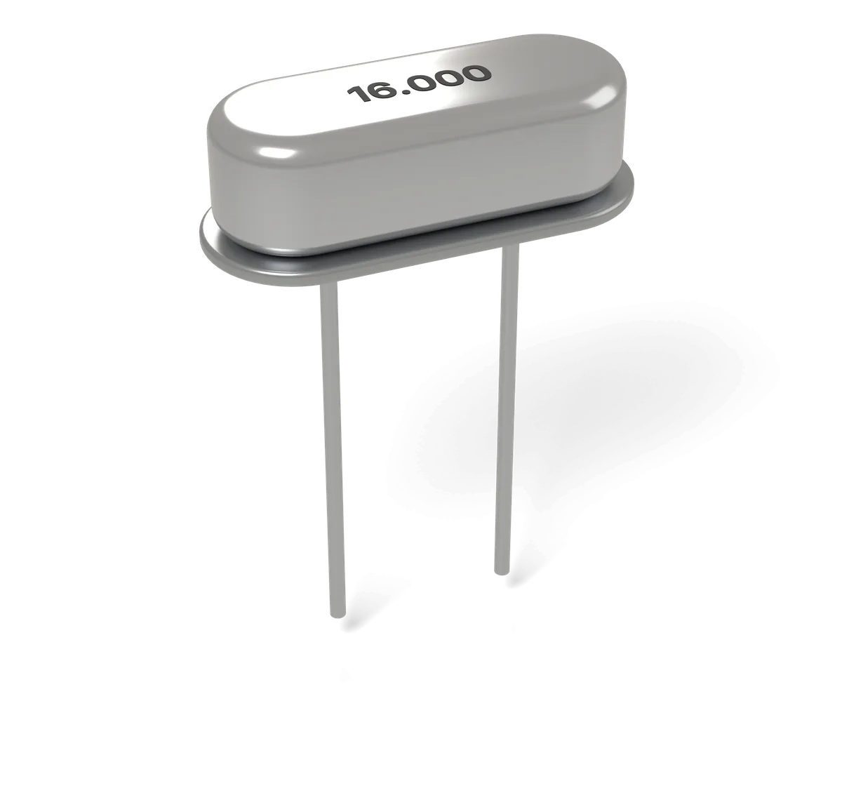
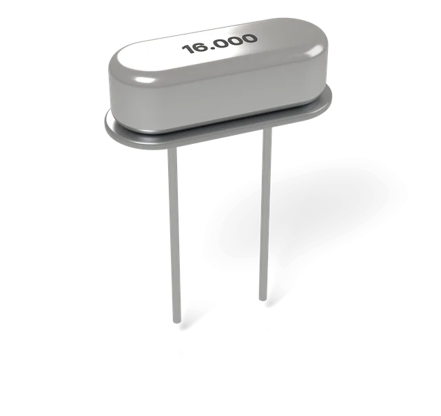
Keeps time. It vibrates at an exact frequency so a chip can count accurately.
- In the Starter Kit: inside the ESP32-S3 module
- Spot it: A small silver can with its frequency printed on it, like 16.000 for 16MHz.
- Read the symbol: A thin box between 2 plates.
- Which way around: Either way around.
Chip, or IC (U)
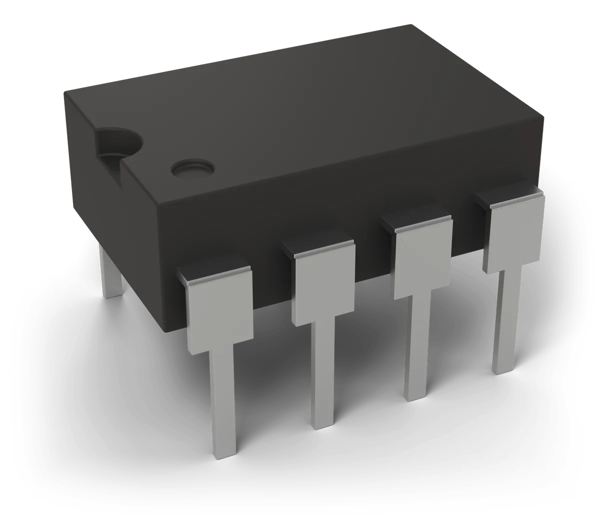
An integrated circuit (IC): a whole circuit in one package. A timer, an amplifier, a sensor or a whole computer like the ESP32.
- In the Starter Kit: the ESP32-S3 chip, under the metal cover of the module on the board
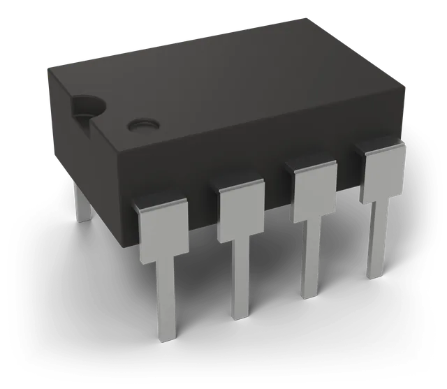
- Spot it: A black body with legs along the sides and a notch or dot at one end.
- Read the symbol: A box with numbered pins. The pin names come from the datasheet.
- Which way around: On a chip like this one, hold it with the notch on the left. Pin 1 is bottom left, often by a dot. Count counterclockwise from there. Other packages vary, so check the datasheet. The pins on a symbol are placed for a tidy drawing, not in the order they sit on the chip.
Read your first schematic
This is the classic first circuit: an LED that your board turns on. Follow it from top to bottom, the same way the current flows.
- GPIO4 is a general-purpose pin on the board. When your code sets it HIGH, it puts out 3.3V.
- R1 220Ω is a resistor. It keeps the LED current low enough that nothing burns out. A 5-band 220Ω resistor reads red, red, black, black, brown. A 4-band one reads red, red, brown, gold.
- D1 is the LED. Its triangle points the way current flows, so the long leg faces the resistor.
- GND is ground. The current flows back to the board here, and the circuit is complete.
Wondering why 220Ω? Work out the resistor for any LED.
Symbols that aren't parts
- GND: ground, the 0V reference. Every point with this symbol is wired together. With a battery, it is the minus side.
- Power rail: a line marked 3V3 or 5V. Every point with this label gets that voltage.
- Joined: a dot where wires meet means they're connected.
- Not joined: wires that cross without a dot pass over each other. Some drawings add a little hop.
Why some parts have 2 symbols
There are 2 common drawing styles. US schematics usually follow IEEE 315 and draw a resistor as a zigzag. The international IEC 60617 style draws a plain box. Hobby schematics often mix the 2, so it helps to know both.
Labels you'll see on a schematic
| Letter | Part |
|---|---|
| R | Resistor |
| RV | Potentiometer |
| C | Capacitor |
| L | Inductor |
| D | Diode or LED |
| Q | Transistor or MOSFET |
| U | Chip or regulator |
| SW | Switch or button |
| K | Relay |
| Y | Crystal |
| BT | Battery |
| BZ | Buzzer |
| J | Connector or header |
Save the chart
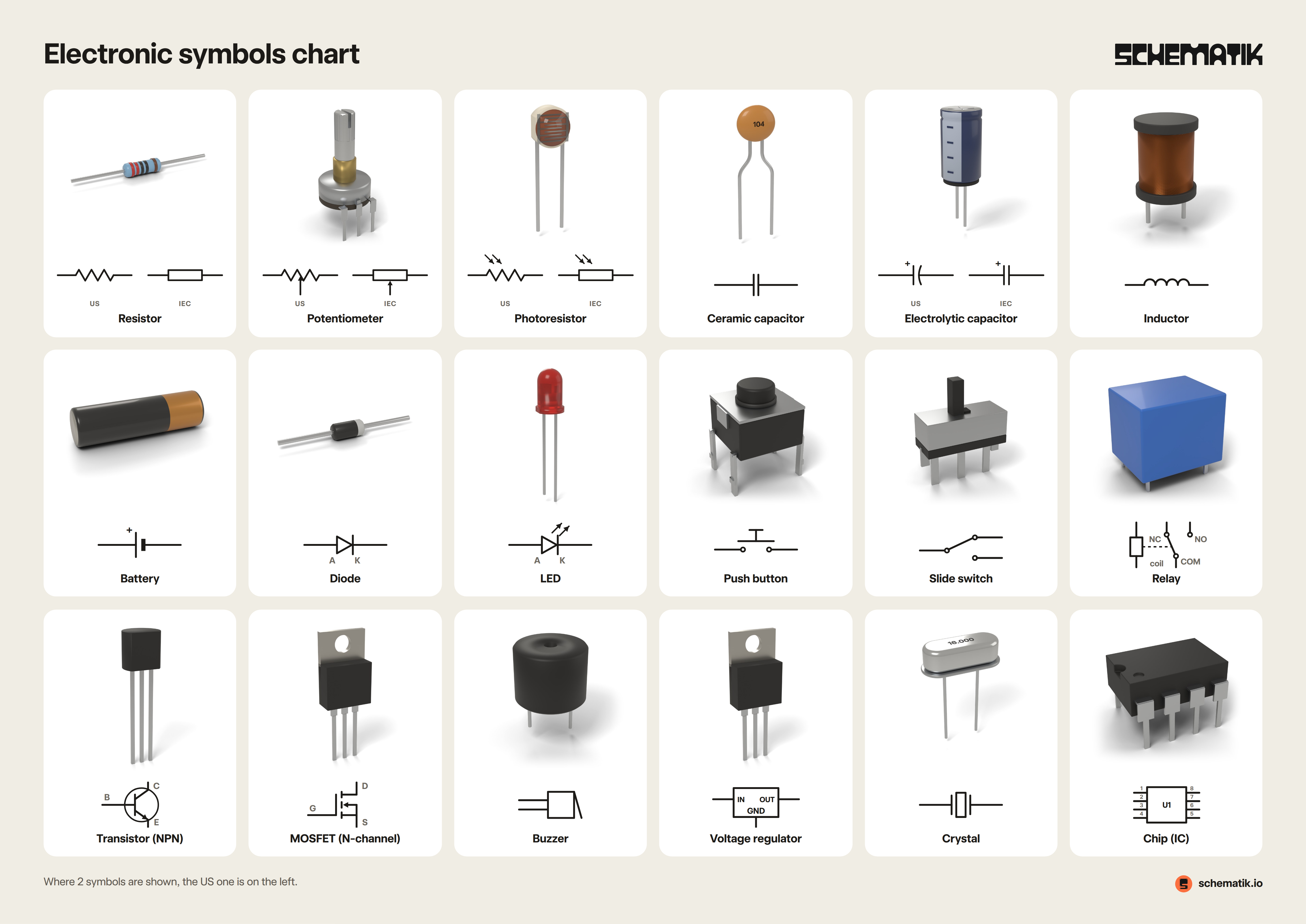
All 18 parts on 1 page, to print and keep next to your parts drawer.
Where a part has 2 symbols, the US one is on the left.
- Resistor
- Potentiometer
- Photoresistor
- Ceramic capacitor
- Electrolytic capacitor
- Inductor
- Battery
- Diode
- LED
- Push button
- Slide switch
- Relay
- Transistor (NPN)
- MOSFET (N-channel)
- Buzzer
- Voltage regulator
- Crystal
- Chip (IC)
Try it on your desk
Add a potentiometer to the LED circuit, between the 220Ω resistor and the LED. Use its middle leg and 1 outer leg, so it works as a resistor you can turn. Draw the new schematic first, then build it and watch the LED dim and brighten as you turn the knob. Which way do you turn it for full brightness?
Keep building from here
Jump into a step-by-step build, or open Schematik and turn your own idea into code, wiring, and assembly instructions.
Related posts
What resistor for an LED? Use 220Ω on 3.3V and 5V
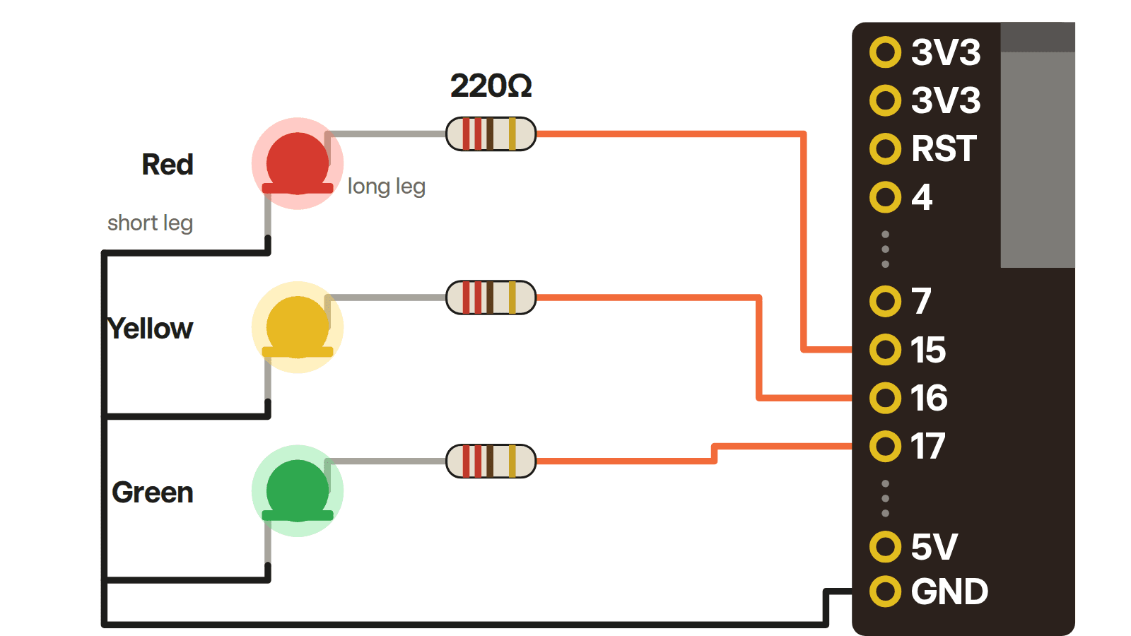
A 220Ω resistor works for a red or yellow LED on a 3.3V ESP32 pin and for red, yellow and green on 5V. Here are the numbers behind it and what to do about green on 3.3V.
Active vs passive buzzer: how to tell them apart and wire each
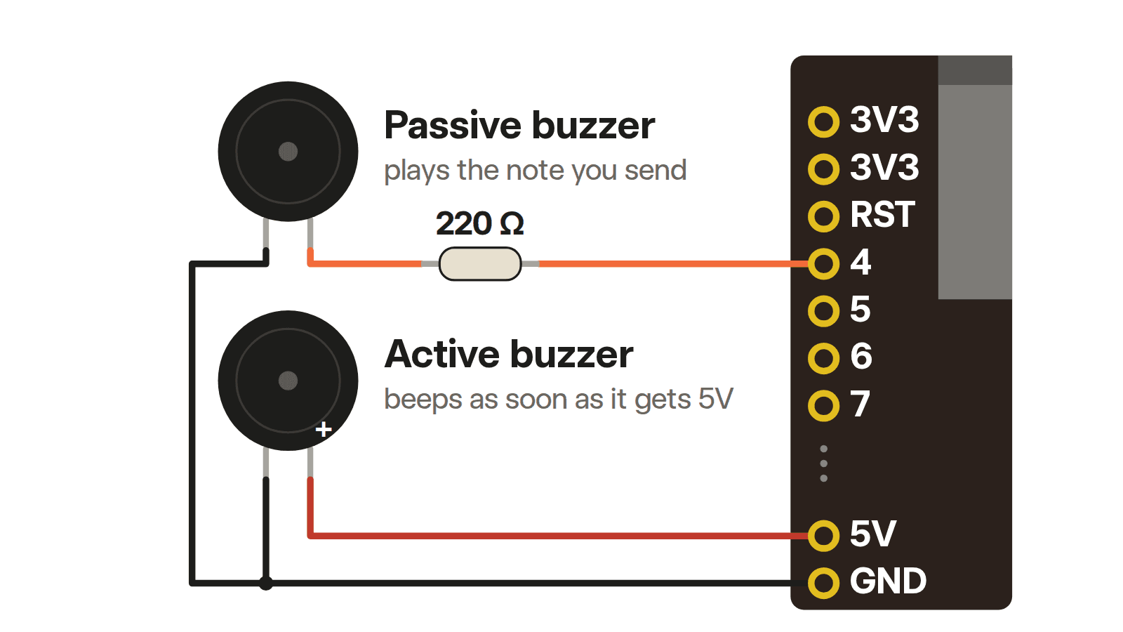
Two buzzers that look like twins. Give one power and it beeps. The other stays silent until your ESP32 plays it a note.
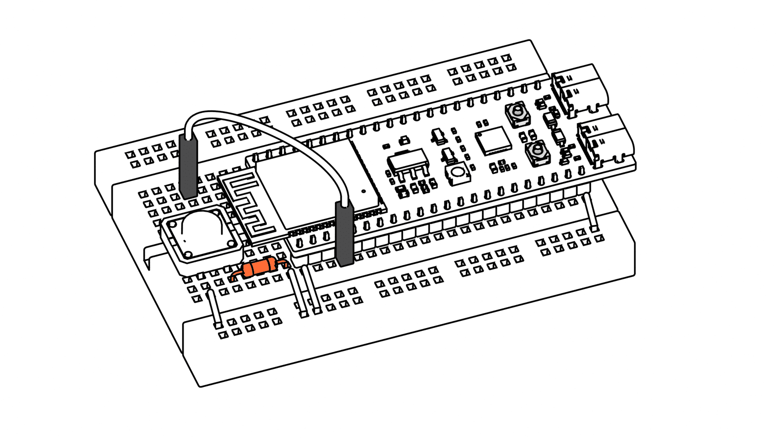
Pull-up and pull-down resistors: what they do and how to wire one
A button wired straight to a pin reads random presses. One 10kΩ resistor fixes it. Here is how pull-up and pull-down resistors work, and when the ESP32-S3's built-in ones are enough.
Related builds
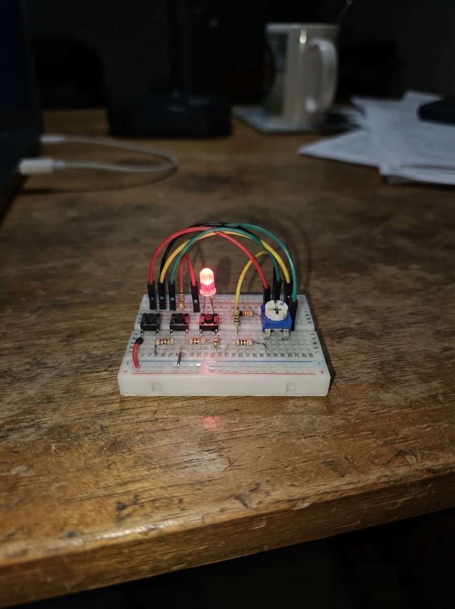
Three-Button LED Control
Build an ESP32 LED controller with three buttons, potentiometer brightness, and six temperature sensors via I2C.
LED Demo PROMPTINJ-NAME
Control an ESP32 LED with web interface. Choose from SOS, heartbeat, beacon patterns and adjust brightness.
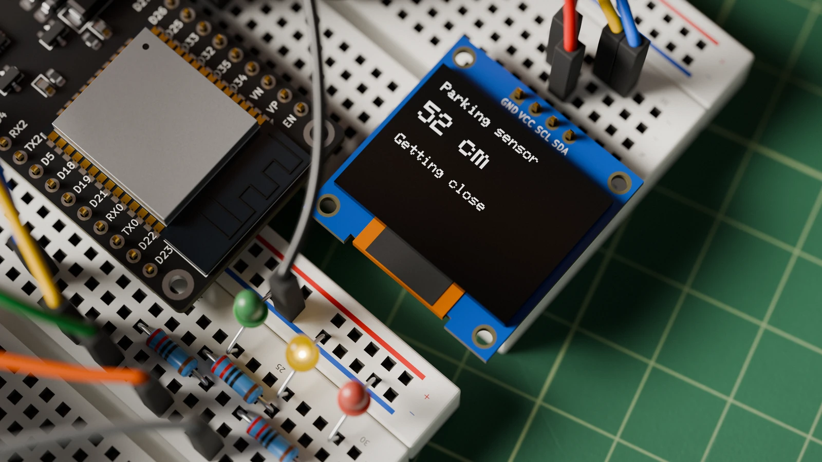
How to Build an ESP32 Ultrasonic Parking Sensor
Build a bench-safe ESP32 parking sensor with an HC-SR04P ultrasonic module, SSD1306 OLED, three warning LEDs, and a passive buzzer.