
On this page
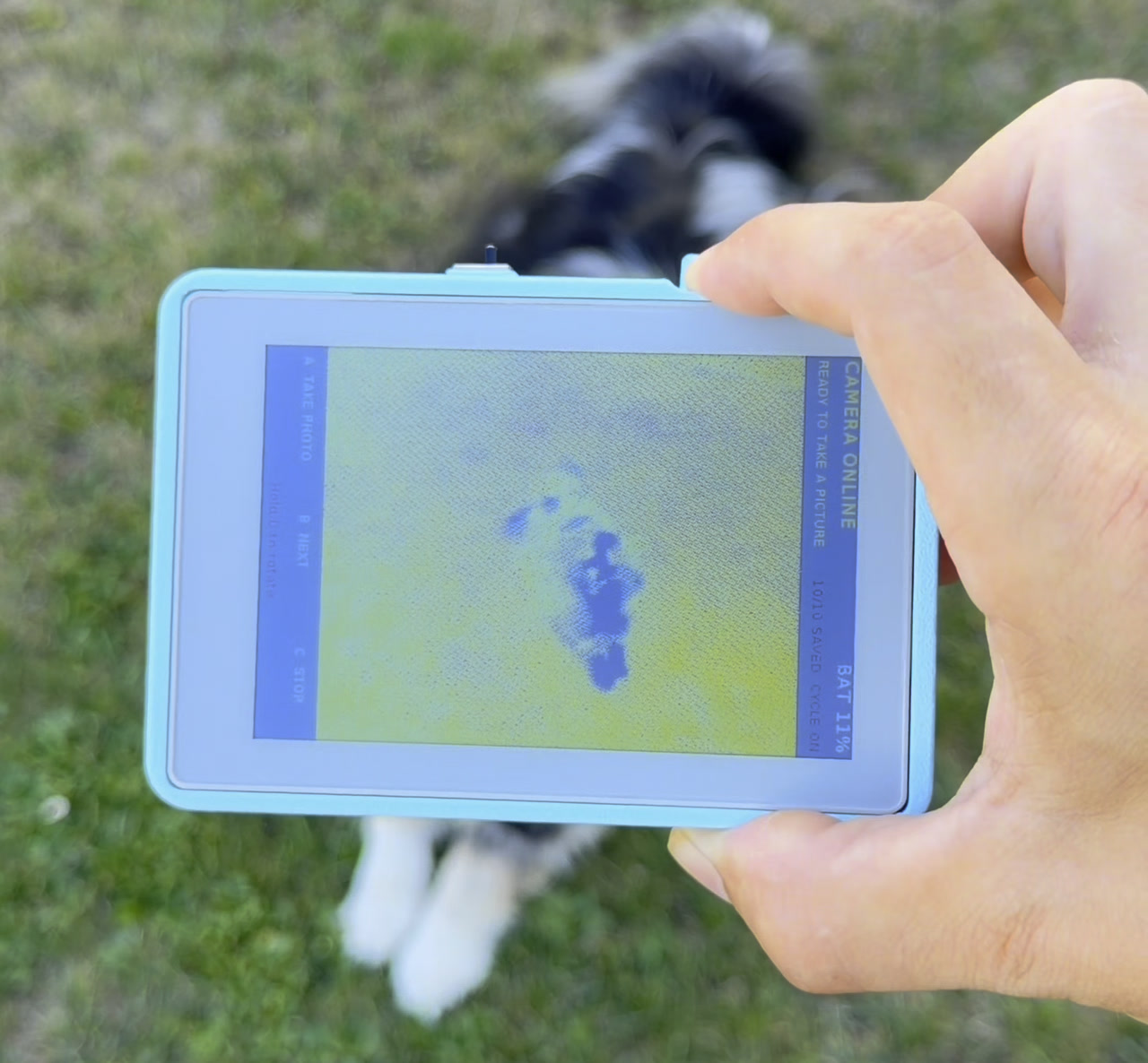
The test that actually mattered happened outside, on the grass. Point the little blue camera at a dog who will not sit still, press the button, and wait. A couple of seconds later the photo turns up on a sheet of colour e-ink — soft, grainy, unmistakably a dog — and then it just stays there, holding the picture with the power off.
That is the whole object, and this is version two of it. A XIAO ESP32S3 Sense takes the photo and hands the JPEG over by ESP-NOW; an M5Stack PaperColor catches it and paints it onto its 4-inch Spectra 6 screen. Both boards live in the same 3D-printed shell — lens out the front, screen out the back — and there is still no wire between them. No router, no SD card, no app.
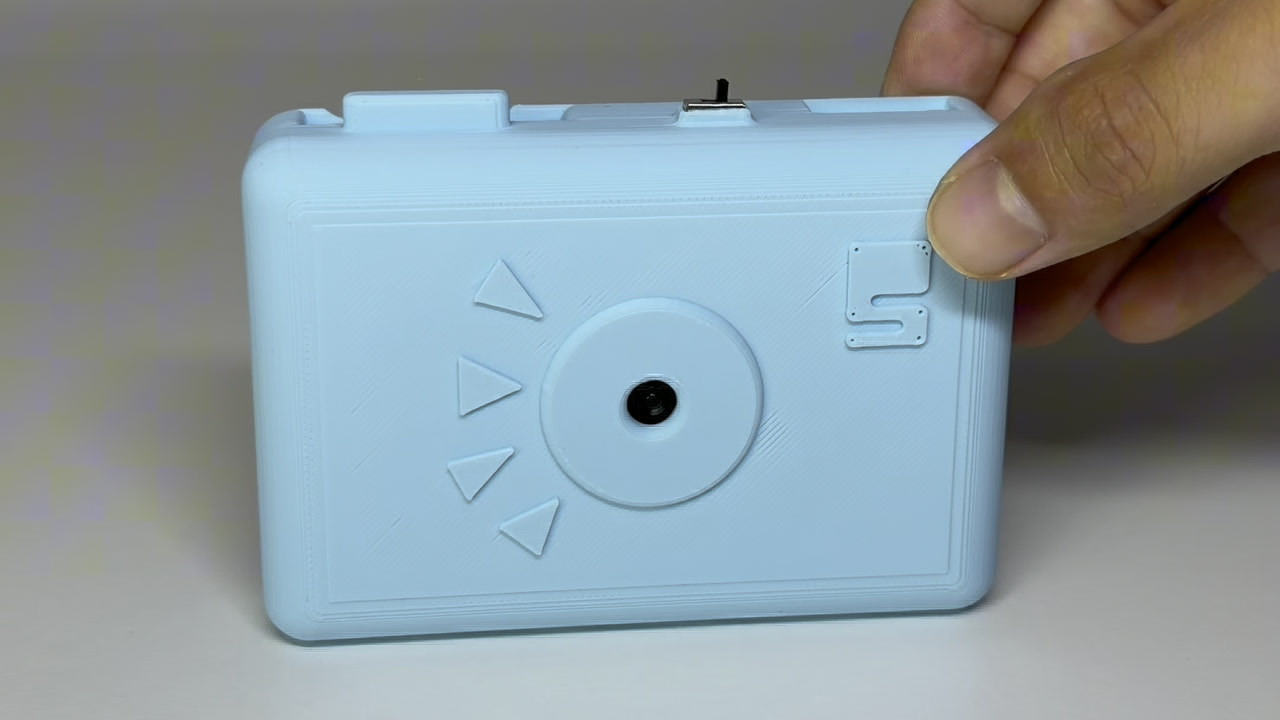
The idea
By any normal spec sheet, e-ink is the wrong screen for a camera, and that is most of the appeal. It is slow and the colour is muted, and it makes you take one picture instead of forty.
The other half of the appeal is that the two boards never share a wire. The XIAO runs the camera off its own LiPo, the PaperColor runs the screen off its own, and the only thing that crosses between them is a radio packet — even though, in the finished object, they are stacked about a centimetre apart. It sounds absurd written down, and it is the reason the build has almost no wiring in it.
Going through a router would have meant depending on one being up, and on two devices agreeing about DHCP before you can take a photo. ESP-NOW skips all of that. Both boards stay in station mode, both get pinned to channel 1, and they talk directly.
Parts that matter
- Seeed Studio XIAO ESP32S3 Sense with the OV3660 camera expansion board
- the little 2.4 GHz external antenna that comes with the XIAO — it clips onto the u.FL connector and it is not optional here, because the whole build is one radio link
- M5Stack PaperColor — the controller: a 4-inch, 600×400 Spectra 6 colour e-ink screen with three front buttons
- a 3.7 V 400 mAh LiPo and a panel-mount SPDT switch for the camera half
- a 3D-printed enclosure for the camera
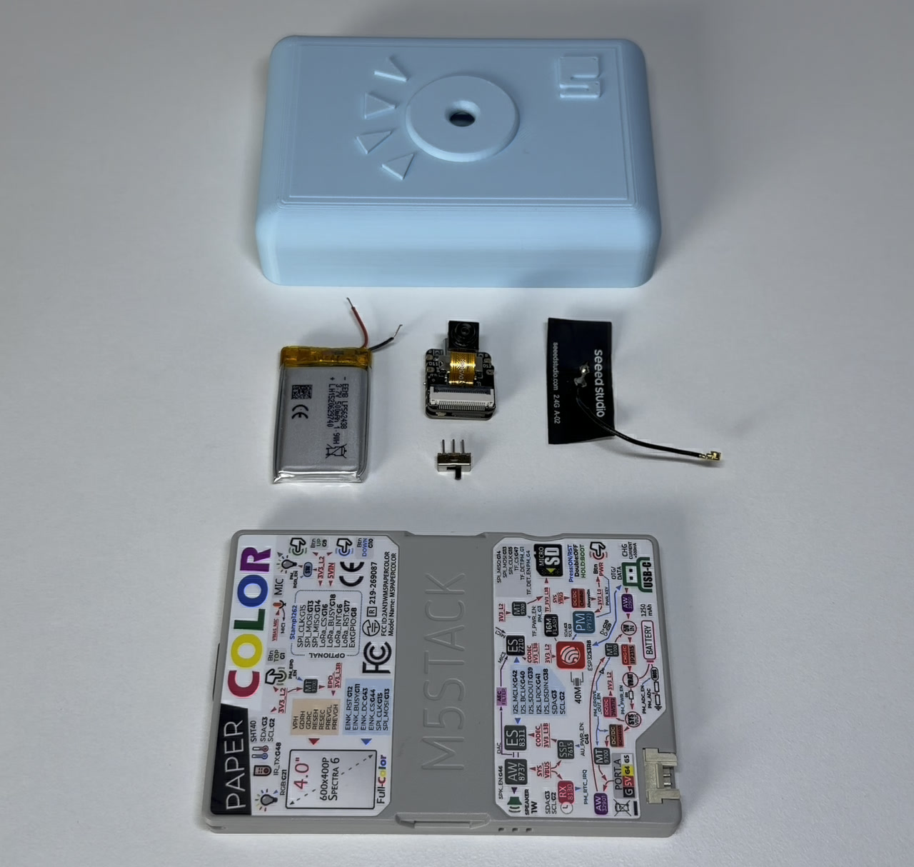
The wiring is almost nothing, which is the point. The PaperColor needs no soldering at all, and there is no wire between the two boards at any point — if you find yourself looking for one, you have misread the build.
Putting it together
Everything goes into one printed shell: lens out the front, screen out the back, both boards stacked inside with a battery each. Everything gets seated first and soldered afterwards, in place. That sounds like the wrong way round until you try it the other way and end up folding a wired-up board into a pocket cut to fit it exactly.
1. Fit the camera board to the XIAO. The OV3660 expansion board is keyed, so it only seats one way round. Do this with both USB and the LiPo disconnected, and keep the lens clean while you are handling it — those camera interface pins belong to the camera and nothing else.
2. Load the shell. The XIAO drops into its recess with the lens looking out through the front hole, the antenna tucks down the side, and the switch sits in the slot on the top edge.
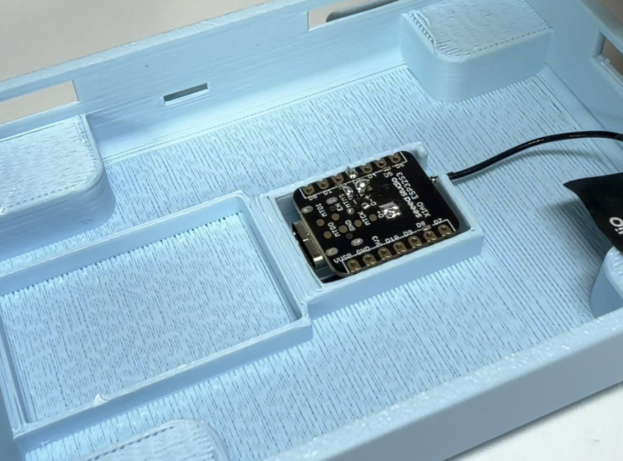
Then the LiPo goes into its own pocket, flat, with the wires folded so they clear the lid.
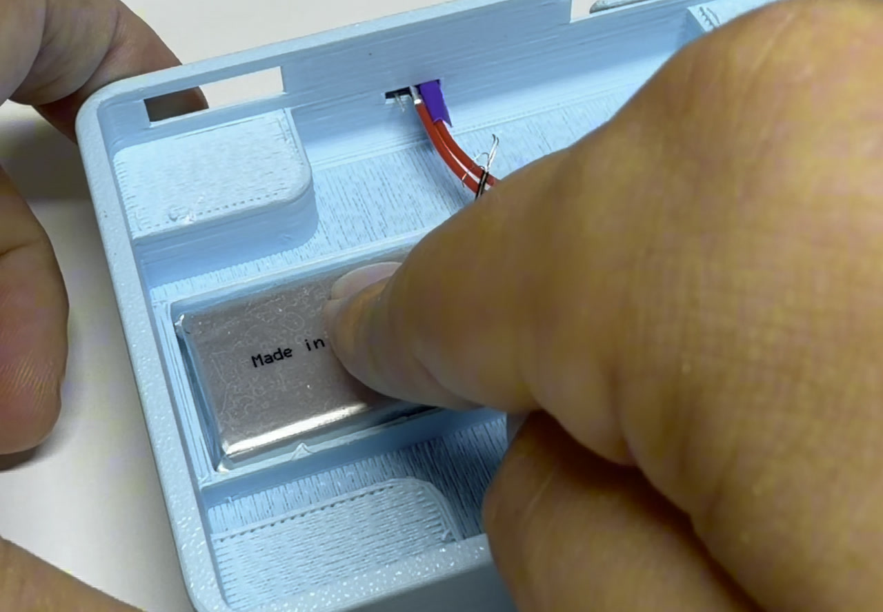
3. Put the switch in the positive wire. Now the soldering, with everything already sitting where it is going to live. The LiPo's red BAT+ wire goes to the switch's COM centre terminal, and one outer terminal — call it NO1 — goes to the XIAO's BAT+ pad. Leave the other outer terminal unconnected. Work out which lever direction you want to mean on before you commit the joint; if it ends up backwards, move the XIAO wire to the other outer terminal rather than unpicking the battery joint.
4. Run the negative wire, then tidy up. The black BAT− wire goes straight to the XIAO's BAT− pad. Both pads are on the back of the XIAO, which is easy to miss until you have the board in your hand turning it over looking for them. Sleeve the joints with heat-shrink and dress the wires so nothing can be pinched when the shell closes.
Reversed battery polarity will damage the XIAO, and a LiPo bridged across both outer switch terminals bypasses the switch entirely and leaves the camera powered forever. Charge only through the XIAO's USB-C port.
That is the camera half finished.
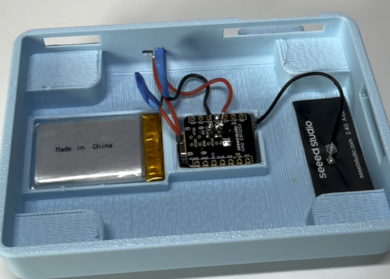
5. Lay the PaperColor on top and close it. This is the part that feels wrong the first time: the display half just goes in. No connector, no jumper, no shared ground — it sits directly above the camera board and the two of them still only speak over the air.
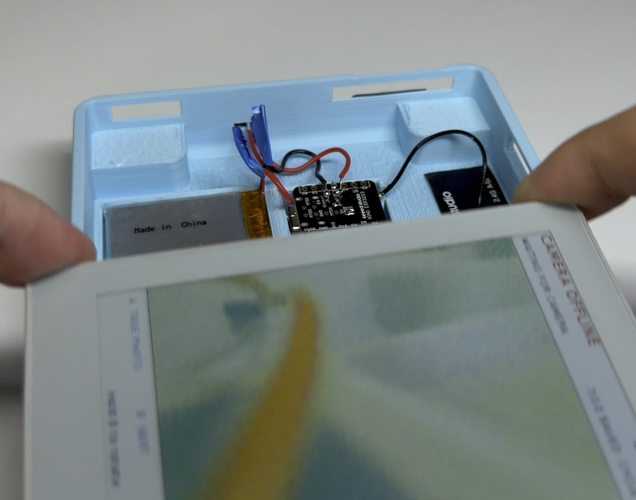
6. Flash both boards, then press A. Deploy the camera firmware to the XIAO and the receiver firmware to the PaperColor, flip the switch on, and press Button A. It sends an ESP-NOW capture request, the XIAO takes a QVGA JPEG, and it comes back to be drawn on the screen. Keep both firmwares on channel 1, and do not let either board join a normal Wi-Fi network while you are using it.
Getting a JPEG through a 250-byte pipe
This is the part worth reading.
ESP-NOW's maximum payload is 250 bytes. A QVGA JPEG at quality 18 is a few kilobytes. So the camera has to slice the frame up and send it as a stream of numbered packets, and the receiver has to put it back together.
The packet is a fixed struct — a magic number ("PCAM"), a type byte, a sequence number, the length fields, and a 232-byte data block. That 232 is not arbitrary: it is what is left after the header, and there is a static_assert in the firmware making sure the whole struct still fits inside ESP_NOW_MAX_DATA_LEN. If you widen the header later, the build fails instead of silently truncating your photos.
The transfer is five packet types: a capture request, an image-start header carrying the total length and dimensions, a run of data chunks, an image-end marker, and an error packet for when the camera has bad news.
The gotcha is pacing. If you fire the chunks in a tight loop you overflow the ESP-NOW transmit queue and the image arrives with holes in it. There are two deliberate pauses in the sender: 12 ms after the start header, and 4 ms between data chunks. They look like the kind of thing you would delete during cleanup. Don't.
One detail I like: the camera never has the display's MAC address compiled into it. It learns who asked by reading info->src_addr off the incoming capture request and replies to that. You can reflash the PaperColor, change boards entirely, and the camera does not care.
Drawing it without freezing the radio
The receiving side has its own trap. It is tempting to decode and draw the image right there inside the ESP-NOW receive callback, because that is where the last packet arrives.
Do not. That callback runs in the Wi-Fi stack's context, and an e-ink refresh is slow — you will stall the radio while the screen updates. The firmware buffers chunks into PSRAM as they land, and the actual drawJpg happens back in the main loop once the end marker shows up. The receiver also carries a 15-second capture timeout and a 700 KB ceiling on the buffer, so a camera that goes quiet halfway through leaves you with a readable error on screen instead of a device that just sits there.
The screen runs in epd_fastest mode. On e-ink, "fastest" is still not fast, and the honest experience is: press Button A, watch it say Capturing…, then a beat, then your photo.
Two firmwares that have to agree
Two boards means two sketches, and they have to agree about things no compiler will check for you: the same channel, the same magic number, the same chunk size, the same packet layout. Nothing in the toolchain catches a mismatch. You find out because nothing arrives.
Each half is its own Schematik project: the camera, the assembly and the printable shell in one, the receiver firmware that runs on the display in the other. Keeping the two open side by side in Schematik is what made the agreeing part manageable. Both boards flash straight from the browser, so moving between the camera firmware and the display firmware is a cable swap and a Deploy click rather than two toolchains — and when the packet struct changed, it changed in both places in the same sitting.
Changes go through the project's agent in plain language, which matters more than it sounds like it should when the alternative is remembering which of two sketches you were editing. The last thing I typed at it was:
remove the text on the display
That status line — CAMERA ONLINE, the button labels, the battery percentage — is genuinely useful while you are still getting the link to work, and then it is just in the way of the photograph. It is still there in the pictures above, so treat that one as unfinished business rather than a before-and-after.
When the link does go quiet, the suspect list is short:
- the two boards sitting on different channels
- one of them accidentally joined to a normal Wi-Fi network
- a chunk size that no longer matches the struct
Serial Monitor on the camera side tells you which one you have.
What I would do next
The obvious upgrades: dithering tuned for the colour e-ink panel instead of relying on drawJpg's defaults, and a deep-sleep mode on the camera so the LiPo lasts days instead of hours.
Paging back through old shots is already in this version — the status line counts saved frames, B steps to the next one, and there is a cycle mode that walks through them on its own. So what is left is mostly finish work: getting that overlay out of the way of the photograph, and making the camera sip power between presses instead of between charges.
If you want to build this one rather than something like it, both halves are published as their own project. Open either in Schematik, flash from the browser, and change whatever you like by asking.


If you want the camera-side fundamentals first, the ESP32-CAM setup portal guide covers those, and the other workshop builds are all in the same shape: one board, one weekend, one specific thing to get working.
Keep building from here
Jump into a step-by-step build, or open Schematik and turn your own idea into code, wiring, and assembly instructions.
Related posts

I Built a Morning Printer That Prints My Day on a Receipt
For week four in the Schematik workshop, I wired an ESP32 to a CSN-A2 thermal printer so it fetches weather and calendar data and leaves a daily briefing on my desk.

I Built an ESP32 Weather Station That Tells Me What to Wear
For week two in the Schematik workshop, I built a tiny ESP32 weather station that checks the forecast and tells me whether to take a jacket, umbrella, sunglasses, shorts, or scarf.
