On this page
Your ESP32-S3 talks in 3.3V. A lot of classic Arduino parts talk in 5V. Wire them straight together and you can hit two problems: the part may not hear what your ESP32 says, or its 5V signal may push more voltage into your ESP32 than its pins are built for.
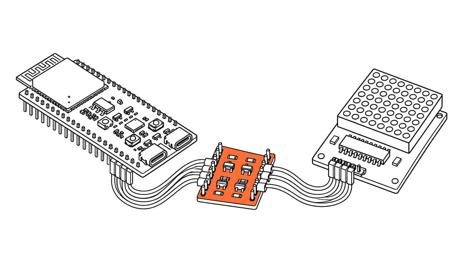
A level shifter sits in the middle and translates. Here's how to tell when you need one, and which one to pick.
What is a logic level?
A GPIO pin (general-purpose input/output, the pins you wire parts to) only says two things: HIGH or LOW. A logic level is the voltage that stands for each one.
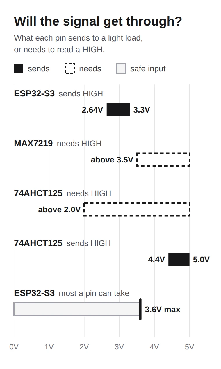
On the ESP32-S3, LOW is close to 0V, the voltage of GND (ground) and HIGH is close to 3.3V, the chip's supply voltage. On a 5V part, HIGH is close to 5V.
The tricky part is that every chip also has a rule for what it will accept as HIGH. The datasheet calls it VIH, the minimum input voltage that counts as HIGH. If the signal you send doesn't reach it, the chip isn't guaranteed to see a HIGH at all.
There are two ways a mismatch goes wrong.
Problem 1: 3.3V is too weak for some 5V parts
The 8×8 LED matrix in the Schematik Starter Kit is driven by a MAX7219 chip. It runs on 4.0V to 5.5V, and its datasheet sets VIH at 3.5V.
Your ESP32-S3's HIGH is at most 3.3V. That's below 3.5V, so the MAX7219 isn't guaranteed to read it. It might work on your desk today and glitch tomorrow, and that kind of bug is miserable to chase.
The fix is to boost the signal up to 5V on its way out.
Problem 2: 5V is too strong for the ESP32-S3
This one can damage your board. With the ESP32-S3 running at 3.3V, Espressif's datasheet rates its GPIO pins for at most 3.6V, its supply plus 0.3V. A 5V part that sends a 5V HIGH into a GPIO pin goes well past that.
The fix is to bring the signal down to about 3.3V on its way in.
Not every 5V part sends 5V back, though. The kit's HC-SR501 motion sensor runs on 5V but its output is 3.3V, so it plugs straight into a GPIO. Check the part's datasheet for its output voltage before you reach for a shifter.
Three ways to shift a logic level
Pick by direction: is the signal going into the ESP32-S3, out of it or both ways on the same wire?
Voltage divider: 5V down into the ESP32-S3
A voltage divider is 2 resistors in a row. The voltage in the middle is a fixed fraction of the voltage at the top.
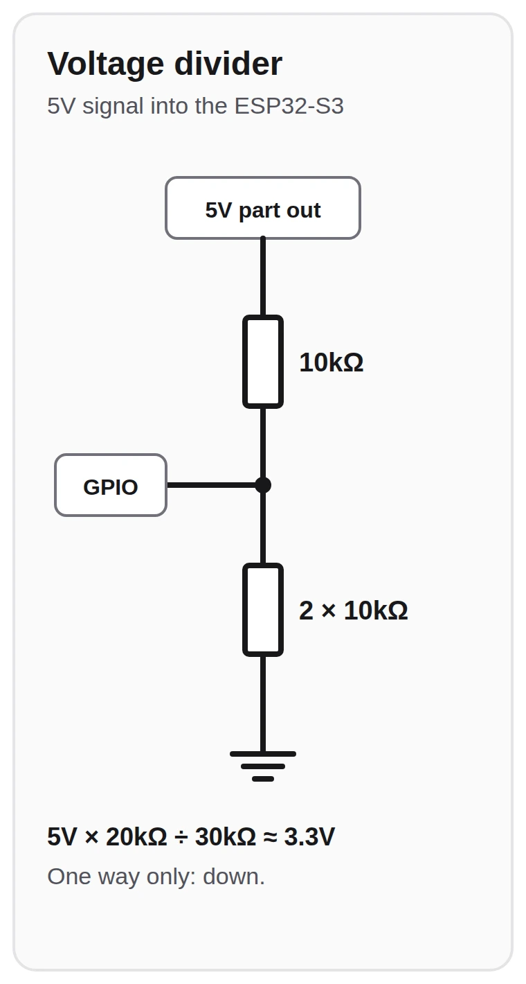
With 10kΩ on top and 20kΩ below, the middle sits at 20 ÷ 30 of the input. A 5V HIGH comes out at about 3.3V, which is safe for the ESP32-S3 and still well above its HIGH threshold of about 2.48V. The kit's resistor packs have 10kΩ, so use 1 on top and 2 in series below.
A divider only works one way, from 5V down to 3.3V. It's a good fit for a slow signal coming out of a 5V sensor. It can't boost a 3.3V signal up.
74AHCT125 buffer: 3.3V up to a 5V part
The 74AHCT125 is a chip with 4 one-way buffers inside. You power it from 5V, and it reads anything above 2V as HIGH. Your 3.3V signal clears that, and the chip sends out a HIGH close to 5V into a logic input like the MAX7219's (at least 4.4V by its datasheet).
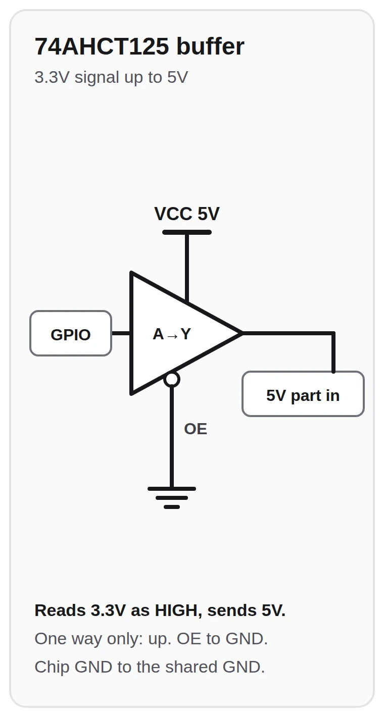
Each buffer has an OE (output enable) pin. Tie it to GND to switch the buffer on. Connect the chip's own GND pin to the same GND as your ESP32-S3 and your 5V part, put a 0.1µF capacitor between its VCC and GND pins and tie any unused A inputs to GND.
This is the one to use for the MAX7219, or any 5V input that needs more than the ESP32-S3's 2.64V to read a HIGH.
MOSFET shifter: both ways, for I2C
I2C, the 2-wire link many screens and sensors use, has SDA for data and SCL for the clock. Data goes both ways on SDA. Parts on the bus only pull a wire LOW or let it go, and a pull-up resistor brings a released wire back to HIGH. A divider or a buffer only works one way, so I2C needs a bidirectional shifter.
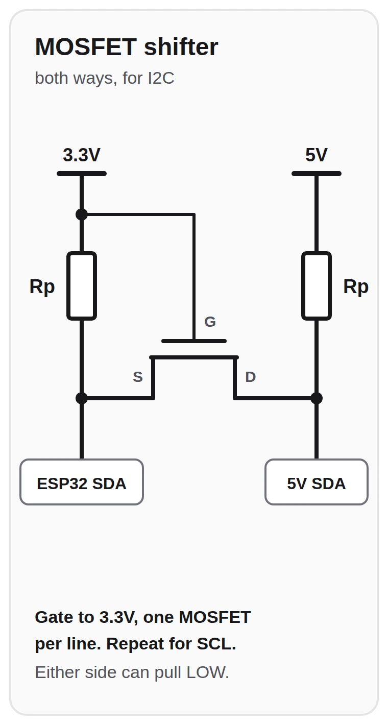
The classic circuit, from NXP's application note AN10441, uses 1 small MOSFET (a transistor that works like a voltage-controlled switch) per wire. Each side keeps its own pull-up resistor to its own supply. When either side pulls the line LOW, the MOSFET switches on and pulls the other side LOW too. When both let go, each side's pull-up brings it back to its own HIGH.
You don't need to build it yourself. A 4-channel bidirectional logic level converter puts 4 of these circuits on one small board. Wire LV to 3.3V, HV to 5V and GND to GND. Then connect the ESP32-S3's SDA and SCL to 2 of the A pins on the low side, and the 5V module's SDA and SCL to the matching B pins on the high side.
Which level shifter do you need?
| Signal | Example | Use |
|---|---|---|
| 5V part → ESP32-S3 | a 5V HC-SR04's Echo pin | voltage divider |
| ESP32-S3 → 5V part | MAX7219 LED matrix | 74AHCT125 |
| Both ways on one wire | I2C to a 5V-only module | MOSFET level converter |
| Part outputs 3.3V | HC-SR501 motion sensor | no shifter |
Choosing a part that runs at 3.3V can avoid the need for a level shifter. Many popular modules come in a 3.3V version, so check before you buy. The classic 5V ultrasonic distance sensor, the HC-SR04, has one: the HC-SR04P. The HC-SR04 vs VL53L0X guide covers which HC-SR04 boards run at 3.3V and how to wire the 5V ones.
Build it with a 3.3V part
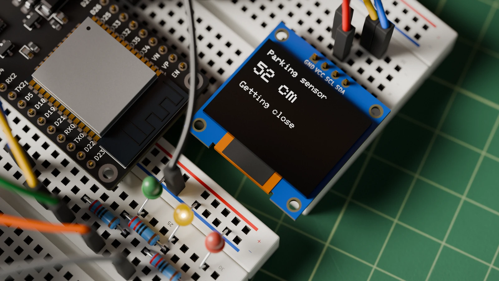
The ESP32 ultrasonic parking sensor is a tabletop distance-warning box. It measures how close an object is and shows it on LEDs, a buzzer and an OLED screen. It uses the HC-SR04P, the 3.3V version of the classic sensor, so it needs no level shifter at all. Open it in Schematik to get the wiring, the parts list and the code, then press Deploy to send it to your board.
Look through the parts on your desk. Which ones run on 5V, and which way do their signals go?
Keep building from here
Jump into a step-by-step build, or open Schematik and turn your own idea into code, wiring, and assembly instructions.