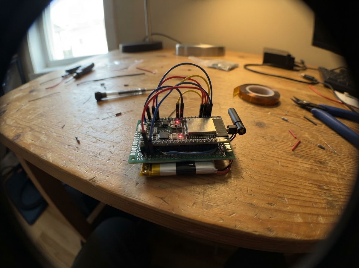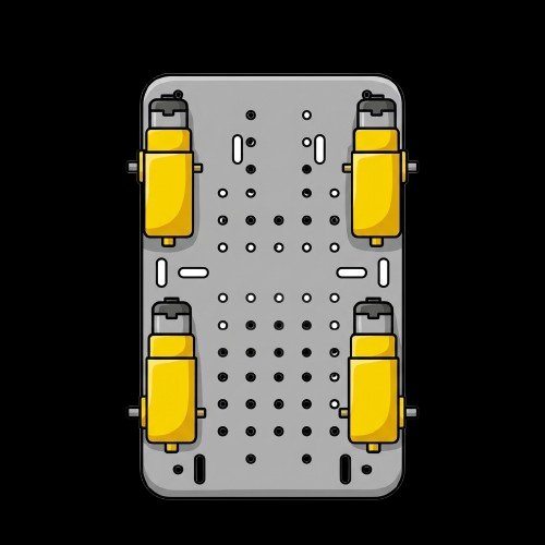
This agricultural monitoring system uses an ESP32 to track soil moisture, temperature, and humidity while controlling irrigation and motorized equipment. The setup combines low-voltage environmental sensors (BMP280, DHT22) with a 12V power system that drives a dosing pump, Mecanum wheel motor, and servo actuator, all coordinated through an RFID reader and I2C expander for flexible field deployment.
The guide provides a complete wiring diagram, parts list, and step-by-step assembly instructions for connecting the sensor array and motor control rails. Firmware examples demonstrate soil moisture monitoring with pump automation, RFID-based command reception via ESP-NOW wireless protocol, and real-time serial logging of system status.
Wiring diagram
Gather all the parts
Assemble it in 2 steps
1. Wire the low-voltage sensors
Use 3.3 V only. RC522 SDA means SPI chip select. Set PCF8574 address straps all low. Use breakouts with I2C pull-ups to 3.3 V.
2. Wire the motor and actuator rails
Use the DFRobot E/M version of the driver, not a generic IN1–IN4 board. Set buck to 5.0 V before connecting loads. Share ground; do not connect actuator positive to USB-powered ESP32. Check total stall and pump/servo current against supply, driver and buck ratings. Raise wheels and disconnect linkages for first tests. Use plain water only and a blunt guarded demonstration plunger.
Review all connections
1. Connections between "supply" and "ESP32"
2. Connections between "buck" and "ESP32"
3. Connections between "bmp" and "ESP32"
4. Connections between "dht" and "ESP32"
5. Connections between "dhtpull" and "ESP32"
6. Connections between "rfid" and "ESP32"
7. Connections between "dir" and "ESP32"
8. Connections between "drive1" and "ESP32"
9. Connections between "wheel1" and "ESP32"
10. Connections between "wheel1pull" and "ESP32"
11. Connections between "wheel2" and "ESP32"
12. Connections between "wheel2pull" and "ESP32"
13. Connections between "drive2" and "ESP32"
14. Connections between "wheel3" and "ESP32"
15. Connections between "wheel3pull" and "ESP32"
16. Connections between "wheel4" and "ESP32"
17. Connections between "wheel4pull" and "ESP32"
18. Connections between "nozzle" and "ESP32"
19. Connections between "punch" and "ESP32"
20. Connections between "dose" and "ESP32"
21. Connections between "dosefet" and "ESP32"
22. Connections between "dosediode" and "ESP32"
23. Connections between "dosepull" and "ESP32"
24. Connections between "dosefetseries" and "ESP32"
25. Connections between "shift" and "ESP32"
Deploy the firmware
#include <Arduino.h>
#if defined(ARDUINO_ARCH_AVR)
static constexpr int pump=7, on=450, off=370;
static constexpr int marks[]={130,260,390,520};
bool running=false, timeout=false;
uint32_t started=0;
void setup(){Serial.begin(115200);pinMode(pump,OUTPUT);for(int i=2;i<=5;++i)pinMode(i,OUTPUT);}
void loop(){
 int sum=0;for(int i=0;i<8;++i)sum+=analogRead(A0);int wet=sum/8;
 if(wet<=off){running=false;timeout=false;}
 if(wet>=on&&!running&&!timeout){running=true;started=millis();}
 if(running&&millis()-started>=15000){running=false;timeout=true;}
 digitalWrite(pump,running);for(int i=0;i<4;++i)digitalWrite(i+2,wet>=marks[i]);
 Serial.print(wet);Serial.print(" pump=");Serial.println(timeout?"TIMEOUT":running?"ON":"OFF");delay(200);
}
#elif defined(ARDUINO_ARCH_ESP32)
#include <WiFi.h>
#include <esp_now.h>
#include <esp_wifi.h>
#include <esp_idf_version.h>
#include <ESP32Servo.h>
#include "NodeConfig.h"
static constexpr uint8_t channel=1;
static bool radio=false;
static portMUX_TYPE mux=portMUX_INITIALIZER_UNLOCKED;
static char queued=0;
static void receive(
#if ESP_IDF_VERSION_MAJOR >= 5
 const esp_now_recv_info_t* info,
#else
 const uint8_t* mac,
#endif
 const uint8_t* data,int n){
#if ESP_IDF_VERSION_MAJOR >= 5
 const uint8_t* mac=info->src_addr;
#endif
 if(n!=1 || memcmp(mac,consoleMac,6))return;
 portENTER_CRITICAL(&mux);queued=static_cast<char>(data[0]);portEXIT_CRITICAL(&mux);
}
static char command(){portENTER_CRITICAL(&mux);char c=queued;queued=0;portEXIT_CRITICAL(&mux);return c;}
static void startRadio(){
 WiFi.mode(WIFI_STA);esp_wifi_set_channel(channel,WIFI_SECOND_CHAN_NONE);Serial.println(WiFi.macAddress());
 uint8_t zero[6]={};if(!memcmp(consoleMac,zero,6)||esp_now_init()!=ESP_OK)return;
 esp_now_peer_info_t peer={};memcpy(peer.peer_addr,consoleMac,6);peer.channel=channel;peer.ifidx=WIFI_IF_STA;
 radio=esp_now_add_peer(&peer)==ESP_OK;if(radio)esp_now_register_recv_cb(receive);
}
static void report(const char* s){Serial.println(s);if(radio)esp_now_send(consoleMac,(const uint8_t*)s,strlen(s));}
#if ANNA_NODE
Servo gate;
bool gasAlarm=false, gateOpen=false;
char mode='A';
uint32_t nextRead=0;
// Values are ADC counts after the divider; calibrate against a warmed-up module.
constexpr int gasOn=2400,gasOff=2100;
void setup(){Serial.begin(115200);pinMode(25,OUTPUT);pinMode(26,INPUT_PULLUP);gate.attach(13,1000,2000);gate.write(0);startRadio();}
void loop(){
 char c=command();if(c=='A'||c=='O'||c=='C')mode=c;
 bool local=!digitalRead(26);bool warm=millis()>=180000;
 int gasPin=34; int x=0;for(int i=0;i<16;++i)x+=analogRead(gasPin);x/=16;
 if(warm){if(x>=gasOn)gasAlarm=true;else if(x<=gasOff)gasAlarm=false;}
 bool open=local||gasAlarm||mode=='O';if(open!=gateOpen){gateOpen=open;gate.write(open?90:0);}digitalWrite(25,open);
 if(millis()-nextRead>=1000){nextRead=millis();char s[128];snprintf(s,sizeof(s),"ANNA,%d,%d,%d,%d,%c,%d",x,gateOpen,open,gasAlarm,local?'L':mode,warm);report(s);}delay(20);
}
#else
#include <Wire.h>
#include <SPI.h>
#include <Adafruit_BMP280.h>
#include <DHT.h>
#include <MFRC522.h>
DHT dht(32,DHT22);
Adafruit_BMP280 bmp;
MFRC522 rfid(4,255);
Servo nozzle,punch;
const uint8_t enablePins[]={14,27,26,16};
bool unlocked=false,bmpOK=false,denied=false,critLatched=false;
uint32_t driveAt=0,lastRead=0,actionAt=0;
char motion='S',action='S';
int phase=0;
void stop(){for(auto p:enablePins)digitalWrite(p,LOW);motion='S';}
void abortAction(){digitalWrite(33,LOW);nozzle.write(20);punch.write(20);action='S';phase=0;}
void drive(char c){
 const char* keys="FBLRQE";const uint8_t patterns[]={0,15,9,6,5,10};const char* k=strchr(keys,c);if(!k||!c)return;
 if(motion==c){driveAt=millis();return;}
 stop();Wire.beginTransmission(0x20);Wire.write(uint8_t(0xF0|patterns[k-keys]));if(Wire.endTransmission())return;
 for(auto p:enablePins)digitalWrite(p,HIGH);motion=c;driveAt=millis();
}
void beginAction(char c){stop();action=c;phase=0;actionAt=millis();if(c=='D')nozzle.write(75);else punch.write(60);}
void setup(){
 Serial.begin(115200);for(auto p:enablePins)pinMode(p,OUTPUT);stop();pinMode(33,OUTPUT);digitalWrite(33,LOW);
 Wire.begin(21,22);bmpOK=bmp.begin(0x76)||bmp.begin(0x77);dht.begin();SPI.begin(18,19,23,4);rfid.PCD_Init();
 nozzle.attach(13,1000,2000);punch.attach(25,1000,2000);abortAction();startRadio();
}
void loop(){
 if(rfid.PICC_IsNewCardPresent()&&rfid.PICC_ReadCardSerial()){
  Serial.print("UID:");for(int i=0;i<rfid.uid.size;i++)Serial.printf(" %02X",rfid.uid.uidByte[i]);Serial.println();
  if(keyLength&&rfid.uid.size==keyLength&&!memcmp(rfid.uid.uidByte,keyUid,keyLength)){unlocked=!unlocked;stop();abortAction();denied=false;command();}
  else{denied=true;unlocked=false;stop();abortAction();}
  rfid.PICC_HaltA();rfid.PCD_StopCrypto1();
 }
 uint32_t now=millis();char c=command();
 if(c=='S'){stop();abortAction();}
 if(motion!='S'&&now-driveAt>450)stop();
 if(unlocked&&action=='S'&&c&&c!='S'){
   if(c=='D'||c=='W')beginAction(c);else drive(c);
 }
 if(action=='D'&&now-actionAt>=400){if(!phase){digitalWrite(33,HIGH);phase=1;actionAt=now;}else abortAction();}
 if(action=='W'&&now-actionAt>=350)abortAction();
 if(now-lastRead>=2500){
  lastRead=now;float h=dht.readHumidity(),t=bmpOK?bmp.readTemperature():dht.readTemperature();float p=bmpOK?bmp.readPressure()/100.0f:NAN;
  float v=(isfinite(t)&&h>=0&&h<=100)?0.6108f*expf(17.27f*t/(t+237.3f))*(1-h/100):NAN;
  bool critical=isfinite(v)&&v<0.8f;
  if(!critical&&isfinite(v))critLatched=false;
  if(critical&&unlocked&&!critLatched&&action=='S'&&c!='S'){beginAction('D');critLatched=true;}
  const char* risk=!isfinite(v)?"INVALID":v<0.8?"CRITICAL":v<1.2?"HIGH":v<1.6?"MODERATE":v<2?"LOW":"DRY";
  char s[160];snprintf(s,sizeof(s),"KRISHI,%.2f,%.2f,%.2f,%.3f,%s,%d,%c,%c,%d",t,h,p,v,risk,unlocked,motion,action,denied);report(s);
 }
 delay(5);
}
#endif
#endif
Remix this project
Make it yours in one click
Open a full copy of this project in your own Schematik workspace, diagram, code, parts, and assembly steps included. Swap the sensor, add features, or redesign the whole thing with AI. The author's original stays untouched.