Community project
AI Pet Safety Collar
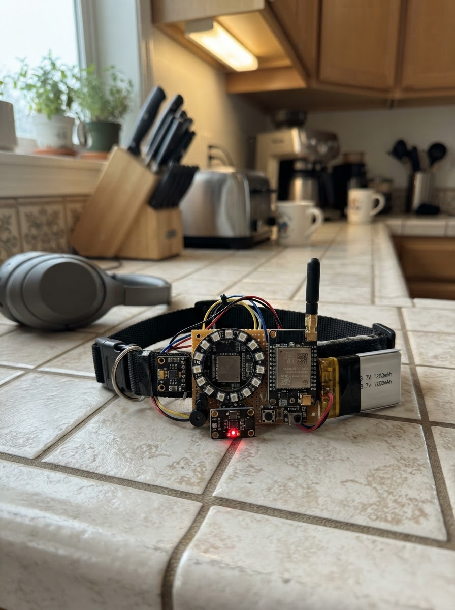
This AI Pet Safety Collar combines cellular connectivity, motion tracking, and health monitoring to keep pets safe and connected. Built around an ESP32 microcontroller, the collar integrates an LTE modem for real-time location updates, a 6-axis motion sensor to detect activity patterns, and a heart rate sensor to monitor pet wellness. The collar also features audio and visual alerts, an emergency SOS button, and a built-in microphone for sound detection.
This guide provides a complete parts list, wiring diagram, and step-by-step assembly instructions for building a functional pet safety device. The included firmware handles sensor data collection, cellular communication, and alert management. Builders will learn how to integrate multiple sensors with an ESP32, manage power delivery for extended battery life, and implement remote notification capabilities using LTE connectivity.
Wiring diagram

Gather all the parts
Assemble it in 6 steps
1. 准备安全供电与外壳
将1200 mAh 保护板锂电池放入隔离仓,TP4056充电板靠近磁吸充电口;不要让电池被项圈弯折、挤压或被狗咬到。
- 电池必须使用带保护板的单节锂电池。
- TP4056充电电流应按电池制造商允许值设置。
- 锂电池不可短路、刺穿或在无人看管时充电。
- 本原型的S7V8F5仅适合低功率验证;A7670E发射时有电流尖峰,量产须改为经验证的5V、至少2A峰值能力电源和足够低ESR储能电容。
2. 连接充电与5V电源链
电池BAT+接充电板B+,BAT-接B-。充电板OUT+接升降压模块VIN,OUT-接其GND。磁吸USB的5V正极接IN+,地线接IN-。升降压模块VOUT形成5V总线。
- 所有模块地线必须共地。
- 先在未接ESP32和4G模块时用万用表确认VOUT为5V。
- 接反锂电池或5V输出会损坏模块并有起火风险。
3. 连接ESP32、运动和心率传感器
ESP32的3.3V分别接MPU6050 VIN和MAX30102 VCC;三者GND共地。将两个传感器的SDA并接GPIO8、SCL并接GPIO9。
- MAX30102必须持续、遮光地贴合适合的皮肤区域;犬只毛发和运动会严重影响PPG心率准确度。
- MPU6050应固定在壳体中央,避免在软带上晃动。
- 不要把I2C上拉电阻接到5V,否则会伤害3.3V ESP32 GPIO。
4. 连接4G/GNSS模块
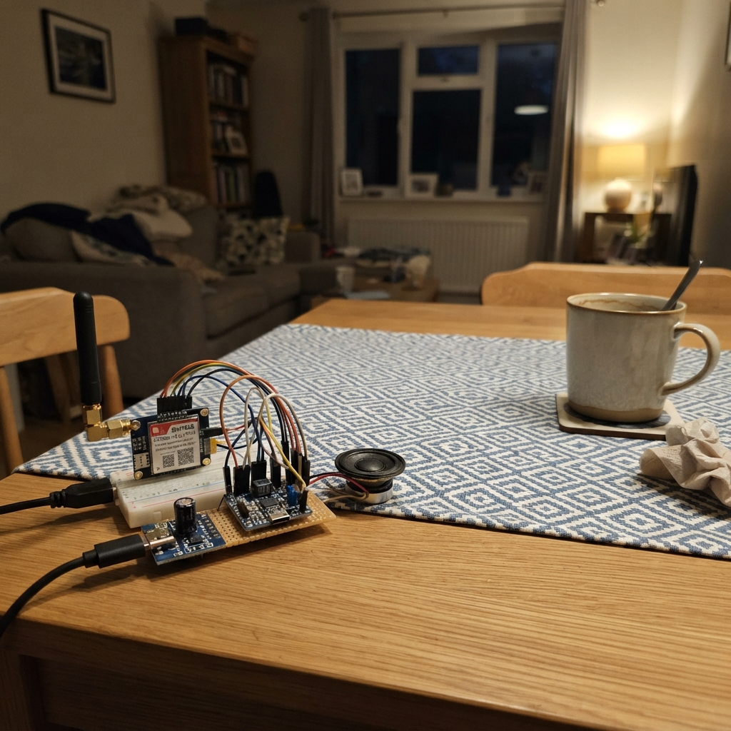
A7670E的VCC接5V总线、GND接公共地、TXD接ESP32 GPIO44、RXD接GPIO43、PWRKEY接GPIO16。安装SIM卡、LTE天线和GNSS陶瓷天线,GNSS天线面向天空且远离人体和金属。
- 若模块载板UART不是3.3V兼容,RXD线上必须加入双向或单向电平转换。
- LTE和GNSS天线同轴线不可挤压或急弯。
- 不要用ESP32的3.3V引脚为A7670E供电。
- 蜂窝通信需使用已开通数据业务且与当地网络兼容的SIM卡。
5. 连接SOS、灯、蜂鸣器与麦克风
SOS按键的一端接地,SIGNAL接GPIO4。WS2812B的DIN接GPIO5、VCC接5V、GND接地;蜂鸣器SIGNAL接GPIO6、GND接地。INMP441的SCK接GPIO12、WS接GPIO11、SD接GPIO13、VDD接3.3V、GND接地、L/R接地。
- 将SOS按键隐藏于主人可按到、犬只不易误触的位置。
- LED数据线靠近LED处可串330Ω;LED电源两端放置约1000µF电容可提高抗干扰能力。
- 若5V WS2812B不识别3.3V数据,增加74AHCT125等3.3V→5V电平转换器。
- 大电流或电磁式蜂鸣器必须经三极管/MOSFET驱动,不能直接接GPIO。
6. 防水封装与台架测试
使用TPU项圈和密封壳,将天线、麦克风声孔、传感器皮肤接触窗分别设计为防水透声/透光结构。先在台架上验证充电、GNSS、SOS、蜂鸣器、LED与串口事件,再佩戴进行短时监督测试。
- 部署固件使用Schematik的Deploy按钮。
- 记录不同犬种和佩戴松紧度下的数据,再校准跌倒与异常声音阈值。
- 不要以本原型替代兽医诊断、紧急救援或持续人工看护。
- IP67/IP68需要成品级密封结构与浸水测试,开发板和洞洞板组合不具备该等级。
Review all connections
1. Connections between "battery" and "ESP32"
2. Connections between "charger" and "ESP32"
3. Connections between "boost_5v" and "ESP32"
4. Connections between "imu" and "ESP32"
5. Connections between "heart_sensor" and "ESP32"
6. Connections between "lte_gnss" and "ESP32"
7. Connections between "sos_button" and "ESP32"
8. Connections between "status_led" and "ESP32"
9. Connections between "buzzer" and "ESP32"
10. Connections between "mic" and "ESP32"
Deploy the firmware
#include <Arduino.h>
#include <Wire.h>
#include <Adafruit_NeoPixel.h>
#include <driver/i2s.h>

#define I2C_SDA 8
#define I2C_SCL 9
#define MODEM_RX 44
#define MODEM_TX 43
#define MODEM_PWRKEY 16
#define SOS_PIN 4
#define LED_PIN 5
#define BUZZER_PIN 6
#define I2S_BCLK 12
#define I2S_WS 11
#define I2S_DATA 13


// Forward declarations
void setStatus(uint32_t color);
void alertTone(uint16_t ms);
void emitEvent(const char *type, const char *detail);
void writeReg(uint8_t addr, uint8_t reg, uint8_t value);
bool readBytes(uint8_t addr, uint8_t reg, uint8_t *out, size_t n);
float readAccelerationG();
uint32_t microphoneEnergy();
void printModem();

static const uint8_t MPU_ADDR = 0x68;
static const uint8_t MAX30102_ADDR = 0x57;
Adafruit_NeoPixel pixel(1, LED_PIN, NEO_GRB + NEO_KHZ800);
HardwareSerial modem(1);
uint32_t lastMotionMs = 0, lastGnssMs = 0, loudSinceMs = 0;
bool sosActive = false;

void setStatus(uint32_t color) { pixel.setPixelColor(0, color); pixel.show(); }
void alertTone(uint16_t ms) { ledcAttach(BUZZER_PIN, 2000, 8); ledcWriteTone(BUZZER_PIN, 2000); delay(ms); ledcWriteTone(BUZZER_PIN, 0); }
void emitEvent(const char *type, const char *detail) {
  Serial.printf("{\"event\":\"%s\",\"detail\":\"%s\",\"uptime_s\":%lu}\n", type, detail, millis() / 1000UL);
  modem.print("AT+CGNSSINFO\r\n");
}
void writeReg(uint8_t addr, uint8_t reg, uint8_t value) {
  Wire.beginTransmission(addr); Wire.write(reg); Wire.write(value); Wire.endTransmission();
}
bool readBytes(uint8_t addr, uint8_t reg, uint8_t *out, size_t n) {
  Wire.beginTransmission(addr); Wire.write(reg);
  if (Wire.endTransmission(false) != 0) return false;
  if (Wire.requestFrom((int)addr, (int)n) != n) return false;
  for (size_t i = 0; i < n; ++i) out[i] = Wire.read();
  return true;
}
float readAccelerationG() {
  uint8_t b[6];
  if (!readBytes(MPU_ADDR, 0x3B, b, sizeof(b))) return -1.0f;
  int16_t ax = (b[0] << 8) | b[1], ay = (b[2] << 8) | b[3], az = (b[4] << 8) | b[5];
  float x = ax / 16384.0f, y = ay / 16384.0f, z = az / 16384.0f;
  return sqrtf(x * x + y * y + z * z);
}
uint32_t microphoneEnergy() {
  int32_t samples[256]; size_t bytesRead = 0;
  i2s_read(I2S_NUM_0, samples, sizeof(samples), &bytesRead, 30 / portTICK_PERIOD_MS);
  uint32_t count = bytesRead / sizeof(int32_t); if (!count) return 0;
  uint64_t total = 0;
  for (uint32_t i = 0; i < count; ++i) total += abs(samples[i] >> 14);
  return (uint32_t)(total / count);
}
void printModem() {
  while (modem.available()) {
    String line = modem.readStringUntil('\n'); line.trim();
    if (line.startsWith("+CGNSSINFO:")) Serial.printf("{\"gnss\":\"%s\"}\n", line.c_str());
  }
}
void setup() {
  Serial.begin(115200);
  pinMode(SOS_PIN, INPUT_PULLUP); pinMode(MODEM_PWRKEY, OUTPUT); digitalWrite(MODEM_PWRKEY, HIGH);
  pixel.begin(); setStatus(pixel.Color(0, 0, 20));
  Wire.begin(I2C_SDA, I2C_SCL); Wire.setClock(400000);
  writeReg(MPU_ADDR, 0x6B, 0x00);
  writeReg(MAX30102_ADDR, 0x09, 0x03);
  modem.begin(115200, SERIAL_8N1, MODEM_RX, MODEM_TX);
  delay(500); modem.print("AT\r\n"); modem.print("AT+CGNSSPWR=1\r\n");
  i2s_config_t config = {};
  config.mode = (i2s_mode_t)(I2S_MODE_MASTER | I2S_MODE_RX); config.sample_rate = 16000;
  config.bits_per_sample = I2S_BITS_PER_SAMPLE_32BIT; config.channel_format = I2S_CHANNEL_FMT_ONLY_LEFT;
  config.communication_format = I2S_COMM_FORMAT_STAND_I2S; config.dma_buf_count = 4; config.dma_buf_len = 128;
  i2s_pin_config_t pins = {};
  pins.bck_io_num = I2S_BCLK; pins.ws_io_num = I2S_WS; pins.data_out_num = I2S_PIN_NO_CHANGE; pins.data_in_num = I2S_DATA;
  i2s_driver_install(I2S_NUM_0, &config, 0, NULL); i2s_set_pin(I2S_NUM_0, &pins);
  emitEvent("boot", "collar prototype started");
}
void loop() {
  printModem();
  if (digitalRead(SOS_PIN) == LOW && !sosActive) {
    sosActive = true; setStatus(pixel.Color(255, 0, 0)); alertTone(300); emitEvent("sos", "manual SOS button pressed");
  }
  if (digitalRead(SOS_PIN) == HIGH) sosActive = false;
  if (millis() - lastMotionMs >= 250) {
    lastMotionMs = millis(); float g = readAccelerationG();
    if (g > 2.8f) { setStatus(pixel.Color(255, 80, 0)); alertTone(100); emitEvent("impact", "high acceleration event"); }
    if (g > 0 && g < 0.18f) emitEvent("possible_fall", "near-free-fall acceleration detected");
    uint8_t prox[2];
    if (readBytes(MAX30102_ADDR, 0xFF, prox, 2) && ((prox[0] << 8) | prox[1]) < 200) Serial.println("{\"health\":\"heart sensor lacks skin contact\"}");
  }
  uint32_t energy = microphoneEnergy();
  if (energy > 1100 && !loudSinceMs) loudSinceMs = millis();
  if (energy <= 1100 && loudSinceMs) {
    if (millis() - loudSinceMs > 10000) emitEvent("abnormal_sound_candidate", "sustained loud sound; trained dog-audio model required for diagnosis");
    loudSinceMs = 0;
  }
  if (millis() - lastGnssMs >= 60000) { lastGnssMs = millis(); modem.print("AT+CGNSSINFO\r\n"); }
  if (!sosActive) setStatus(pixel.Color(0, 10, 0));
}
Remix this project
Make it yours in one click
Open a full copy of this project in your own Schematik workspace — diagram, code, parts, and assembly steps included. Swap the sensor, add features, or redesign the whole thing with AI. The author's original stays untouched.