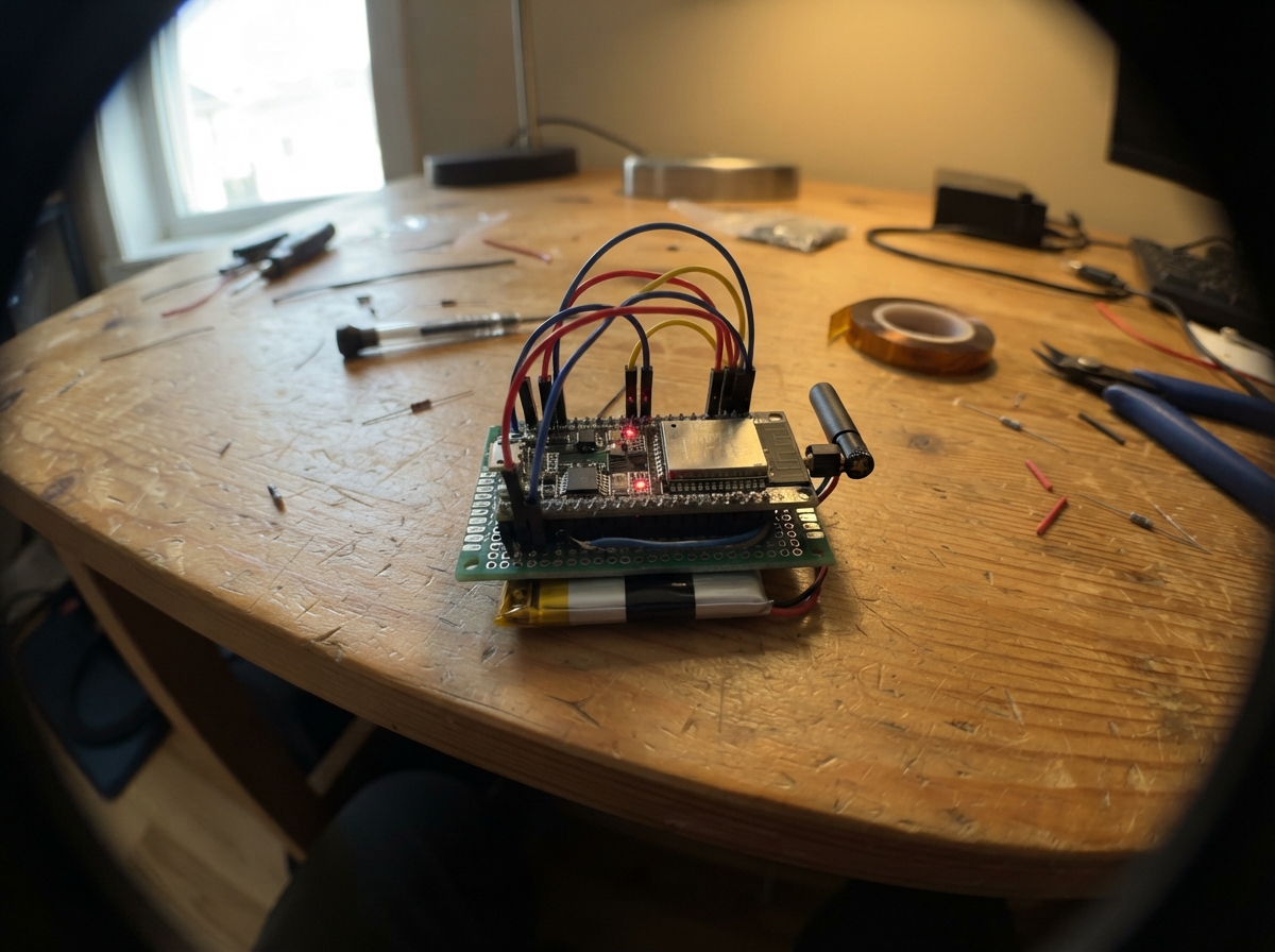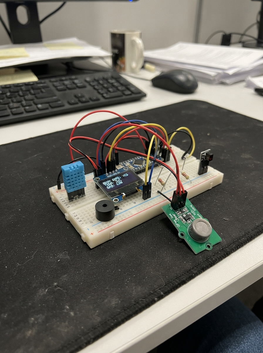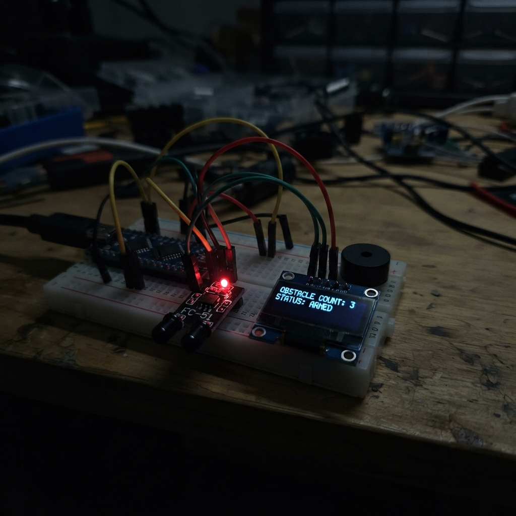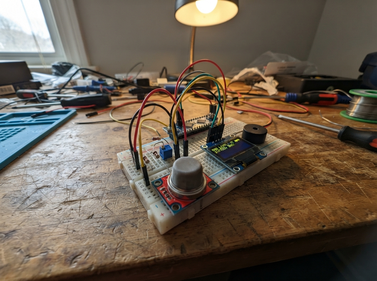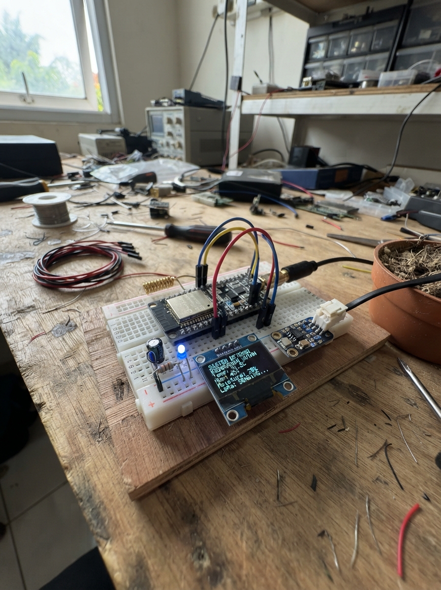
This early forest fire detection system uses an ESP32-based network of remote sensor nodes connected via LoRa radio to a central gateway. Each node monitors temperature, humidity, soil moisture, flame presence, and smoke levels, transmitting alerts when dangerous conditions are detected. The system displays real-time sensor data on local LCD screens and triggers visual and audio alarms at the gateway.
This guide provides a complete wiring diagram, parts list, and step-by-step assembly instructions for building both the distributed sensor nodes and the central gateway station. The included firmware handles LoRa communication, multi-sensor integration, and configurable alert thresholds, allowing makers to deploy an effective early warning network across forest areas.
Wiring diagram
Gather all the parts
Assemble it in 7 steps
1. Pisahkan node dan gateway
ESP32 utama pada gambar adalah node. Rakit gateway di breadboard lain. Masing-masing ESP32 diberi daya lewat USB sendiri. Jangan satukan jalur daya kedua rangkaian. Gunakan adaptor breadboard yang sesuai untuk modul RFM95W dan AO3400A.
2. Pasang radio dan antena
Pasang kapasitor dekat suplai tiap radio, kaki positif ke 3,3 V dan negatif ke GND setempat. Pasang antena cocok pada pad ANT masing-masing RFM95W. Bila menggunakan pigtail coax, inti ke ANT dan pelindung ke GND radio.
- Jangan memancar tanpa antena. Periksa aturan frekuensi dan daya pancar setempat sebelum uji radio.
3. Sambungkan sensor di node
BME280 dan sensor tanah berbagi jalur data GPIO21 dan jalur jam GPIO22. KY-026 memakai 3,3 V dan mengirim sinyal analog ke GPIO35. MQ-2 memakai 5 V. Hubungkan AO MQ-2 lewat resistor atas; GPIO33 berada di titik tengah kedua resistor. Biarkan DO MQ-2 kosong.
- Jangan hubungkan AO MQ-2 langsung ke ESP32. Pastikan pin 5 V DevKit mendapat 5 V dari USB sebelum memasang MQ-2.
4. Pasang lampu, buzzer, dan layar
Tiap LED memakai resistor 330 ohm pada kaki anoda. Hubungkan kaki katoda ke GND board setempat. Di node, buzzer piezo aktif 5 V disakelarkan oleh AO3400A. Di gateway, OLED memakai 3,3 V dengan GPIO21 sebagai data dan GPIO22 sebagai jam.
5. Pasang LCD di node
Pasang konverter BSS138 antara ESP32 dan LCD 5 V. GPIO21 dan GPIO22 masuk ke LV1 dan LV2. HV1 ke SDA LCD dan HV2 ke SCL LCD. Sambungkan LV ke 3,3 V, HV ke 5 V dan satukan GND node dengan GND LCD. Gunakan backpack PCF8574 yang kompatibel dengan LiquidCrystal_I2C (0x27 atau 0x3F).
6. Hubungkan lima STB ke switch
Sambungkan setiap port RJ45 HG680-P ke port LAN switch yang berbeda. Gunakan adaptor daya asli masing-masing STB dan switch. Jangan sambungkan pin internal atau satukan keluaran adaptor. Port kosong bisa menuju router untuk alamat IP otomatis. Setelah kedua ESP32 diisi firmware dan disetel perannya, pindahkan kabel USB data gateway dari komputer ke USB host STB 1 jika sistem operasi STB bisa membaca USB serial. Gunakan 115200 baud. Empat STB lain terhubung melalui LAN; firmware ESP32 tidak menjalankan pengolahan gambar.
7. Terima data di HG680-P 1
Gunakan kabel USB data dari gateway ke USB host STB 1 setelah mengatur peran GATEWAY. Pada STB yang menjalankan Linux dengan dukungan USB serial, instal paket python3-serial yang sesuai distribusinya. Salin data/stb_receiver.py ke STB, cek nama port (/dev/ttyUSB0 atau /dev/ttyACM0), lalu jalankan python3 stb_receiver.py /dev/ttyUSB0. Output berupa satu objek JSON per baris. Tambahkan >> telemetry.jsonl untuk menyimpan log. Lihat data/diagram-berlabel.svg untuk nama setiap komponen.
Review all connections
1. Connections between "node_lora" and "ESP32"
2. Connections between "node_cap" and "ESP32"
3. Connections between "node_green_r" and "ESP32"
4. Connections between "node_green" and "ESP32"
5. Connections between "node_yellow_r" and "ESP32"
6. Connections between "node_yellow" and "ESP32"
7. Connections between "node_red_r" and "ESP32"
8. Connections between "node_red" and "ESP32"
9. Connections between "gw_lora" and "ESP32"
10. Connections between "gw_cap" and "ESP32"
11. Connections between "gw_green_r" and "ESP32"
12. Connections between "gw_green" and "ESP32"
13. Connections between "gw_yellow_r" and "ESP32"
14. Connections between "gw_yellow" and "ESP32"
15. Connections between "gw_red_r" and "ESP32"
16. Connections between "gw_red" and "ESP32"
17. Connections between "oled" and "ESP32"
18. Connections between "bme" and "ESP32"
19. Connections between "soil" and "ESP32"
20. Connections between "flame" and "ESP32"
21. Connections between "mq" and "ESP32"
22. Connections between "mq_top" and "ESP32"
23. Connections between "mq_bottom" and "ESP32"
24. Connections between "alarm" and "ESP32"
25. Connections between "switch" and "ESP32"
26. Connections between "gate_down" and "ESP32"
27. Connections between "stb1" and "ESP32"
28. Connections between "stb2" and "ESP32"
29. Connections between "stb3" and "ESP32"
30. Connections between "stb4" and "ESP32"
31. Connections between "stb5" and "ESP32"
32. Connections between "lcd_shift" and "ESP32"
33. Connections between "lcd" and "ESP32"
34. Connections between "gateway" and "ESP32"
Deploy the firmware
#include <Arduino.h>
#include <Wire.h>
#include <SPI.h>
#include <Preferences.h>
#include <LoRa.h>
#include <Adafruit_BME280.h>
#include <Adafruit_seesaw.h>
#include <Adafruit_SSD1306.h>
#include <LiquidCrystal_I2C.h>

Preferences cfg;
Adafruit_BME280 bme;
Adafruit_seesaw soil;
Adafruit_SSD1306 oled(128,64,&Wire,-1);
LiquidCrystal_I2C lcd27(0x27,16,2), lcd3f(0x3f,16,2);
LiquidCrystal_I2C *lcd=nullptr;
bool gateway, radio, screen, bmeOK, soilOK;
unsigned long lastRx, lastSample, bootAt;
bool received=false;
int statusRx=1, rssi=0;
float t=NAN,h=NAN;
int moisture=-1,mq=0,flame=0;
char oldA[17]={}, oldB[17]={}, oldO[100]={}, command[48]={};
size_t used=0;
unsigned smokeLimit, flameLimit;
int txPower;

bool probe(uint8_t a){ Wire.beginTransmission(a); return Wire.endTransmission()==0; }
void lights(int s){ digitalWrite(25,s==0); digitalWrite(26,s==1); digitalWrite(27,s==2); }
void line(int row,const char *text,char *old){
  char padded[17]; snprintf(padded,sizeof padded,"%-16.16s",text);
  if(lcd && strcmp(padded,old)){ lcd->setCursor(0,row); lcd->print(padded); strcpy(old,padded); }
}
void setup(){
  Serial.begin(115200);
  cfg.begin("forest",false);
  gateway=cfg.getBool("gateway",false);
  smokeLimit=cfg.getUInt("smoke",0); flameLimit=cfg.getUInt("flame",0);
  for(int p:{25,26,27}) pinMode(p,OUTPUT);
  lights(1);
  if(!gateway){ pinMode(32,OUTPUT); digitalWrite(32,LOW); }
  Wire.begin(21,22); Wire.setTimeOut(50);
  if(gateway){
    int addr=probe(0x3c)?0x3c:probe(0x3d)?0x3d:0;
    screen=addr && oled.begin(SSD1306_SWITCHCAPVCC,addr,false,false);
  } else {
    bmeOK=bme.begin(0x77)||bme.begin(0x76);
    soilOK=soil.begin(0x36);
    lcd=probe(0x27)?&lcd27:probe(0x3f)?&lcd3f:nullptr;
    if(lcd){lcd->init();lcd->backlight();}
  }
  unsigned khz=cfg.getUInt("khz",0);
  txPower=cfg.getInt("dbm",2);
  if(khz>=902000 && khz<=928000){
    SPI.begin(18,19,23,4); LoRa.setPins(4,16,17);
    radio=LoRa.begin(khz*1000L);
    if(radio){LoRa.setTxPower(txPower);LoRa.setSyncWord(0x42);LoRa.enableCrc();}
  }
  bootAt=millis(); lastSample=bootAt-5000;
  Serial.printf("ROLE %s RADIO %s\n",gateway?"GATEWAY":"NODE",radio?"ON":khz?"ERROR":"OFF");
  Serial.println("Commands: NODE | GATEWAY | RADIO <kHz> <dBm> | RADIO OFF | THRESH <MQ_mV_min> <IR_mV_max> | TEST");
}
void settings(){
  while(Serial.available()){
    char c=Serial.read();
    if(c=='\r') continue;
    if(c!='\n'){ if(used<sizeof(command)-1) command[used]=c; ++used; continue; }
    if(used>=sizeof(command)){used=0;continue;}
    command[used]=0; used=0;
    unsigned a,b; char extra;
    if(!strcmp(command,"NODE")||!strcmp(command,"GATEWAY"))cfg.putBool("gateway",command[0]=='G');
    else if(!strcmp(command,"RADIO OFF"))cfg.putUInt("khz",0);
    else if(sscanf(command,"RADIO %u %u %c",&a,&b,&extra)==2 && a>=902000 && a<=928000 && b>=2 && b<=17){cfg.putUInt("khz",a);cfg.putInt("dbm",b);}
    else if(sscanf(command,"THRESH %u %u %c",&a,&b,&extra)==2 && a<=2500 && b<=3100){cfg.putUInt("smoke",a);cfg.putUInt("flame",b);}
    else if(!strcmp(command,"TEST") && !gateway){lights(2);digitalWrite(32,HIGH);delay(500);digitalWrite(32,LOW);lastSample=millis()-5000;continue;}
    else continue;
    ESP.restart();
  }
}
int avgMv(int p){int sum=0;for(int i=0;i<12;i++)sum+=analogReadMilliVolts(p);return sum/12;}
void node(unsigned long now){
  if(now-lastSample<2000)return;
  lastSample=now;
  bool hasBme=bmeOK && (probe(0x76)||probe(0x77));
  t=hasBme?bme.readTemperature():NAN; h=hasBme?bme.readHumidity():NAN;
  moisture=soilOK && probe(0x36)?soil.touchRead(0):-1;
  mq=avgMv(33); flame=avgMv(35);
  bool ready=now-bootAt>=180000UL;
  bool smoke=ready && smokeLimit && mq>=int(smokeLimit);
  bool ir=flameLimit && flame<=int(flameLimit);
  // Require agreement for two successive samples before sounding the alarm.
  static int hits=0; hits=smoke && ir?min(2,hits+1):0;
  int s=hits==2?2:(!radio||!ready||!smokeLimit||!flameLimit||smoke||ir||!isfinite(t)||!isfinite(h)||moisture<0)?1:0;
  lights(s);digitalWrite(32,s==2);
  char a[32],b[32],packet[100];
  snprintf(a,sizeof a,"T%.1fC H%.0f%%",t,h);
  snprintf(b,sizeof b,"%s M%d",s==2?"ALARM":!radio?"RADIO OFF":!ready?"PANAS MQ":s==1?"CEK":"NORMAL",mq);
  line(0,a,oldA);line(1,b,oldB);
  snprintf(packet,sizeof packet,"FF1,%d,%.1f,%.1f,%d,%d,%d",s,t,h,moisture,mq,flame);
  Serial.println(packet);
  static unsigned long sent=0;
  if(radio && now-sent>=10000){sent=now; if(LoRa.beginPacket()){LoRa.print(packet);LoRa.endPacket(true);}}
}
void receivePacket(unsigned long now){
  if(!radio || !LoRa.parsePacket()) return;
  char buf[100]; size_t n=0; bool valid=true;
  while(LoRa.available()){int c=LoRa.read();if(n<sizeof(buf)-1 && c>=32 && c<=126)buf[n++]=c;else valid=false;}
  buf[n]=0;
  int s,soilRaw,m,f;float temp,hum;char extra;
  if(!valid || sscanf(buf,"FF1,%d,%f,%f,%d,%d,%d%c",&s,&temp,&hum,&soilRaw,&m,&f,&extra)!=6 || s<0 || s>2 || m<0 || m>3300 || f<0 || f>3300)return;
  statusRx=s;t=temp;h=hum;moisture=soilRaw;mq=m;flame=f;rssi=LoRa.packetRssi();lastRx=now;received=true;
  Serial.printf("%s,%d\n",buf,rssi);
}
void showGateway(unsigned long now){
  receivePacket(now);
  bool online=received&&now-lastRx<35000UL;
  static bool wasOnline=false;
  if(wasOnline && !online)Serial.println("LINK,LOST");
  wasOnline=online;
  lights(online?statusRx:1);
  char msg[100];
  if(!online)snprintf(msg,sizeof msg,"%s",!radio?"RADIO OFF / ERROR":received?"KONEKSI PUTUS":"MENUNGGU NODE");
  else snprintf(msg,sizeof msg,"%s\nT %.1f C H %.0f %%\nTanah %d\nMQ %d IR %d mV\nRSSI %d dBm",statusRx==2?"ALARM":statusRx==1?"CEK NODE":"NORMAL",t,h,moisture,mq,flame,rssi);
  if(screen && strcmp(oldO,msg)){strcpy(oldO,msg);oled.clearDisplay();oled.setCursor(0,0);oled.setTextSize(1);oled.setTextColor(SSD1306_WHITE);oled.print(msg);oled.display();}
}
void loop(){settings();unsigned long now=millis();if(gateway)showGateway(now);else node(now);delay(10);}

// LCD shares GPIO21/22 through the bidirectional translator.
Remix this project
Make it yours in one click
Open a full copy of this project in your own Schematik workspace, diagram, code, parts, and assembly steps included. Swap the sensor, add features, or redesign the whole thing with AI. The author's original stays untouched.