Community project
Untitled Project
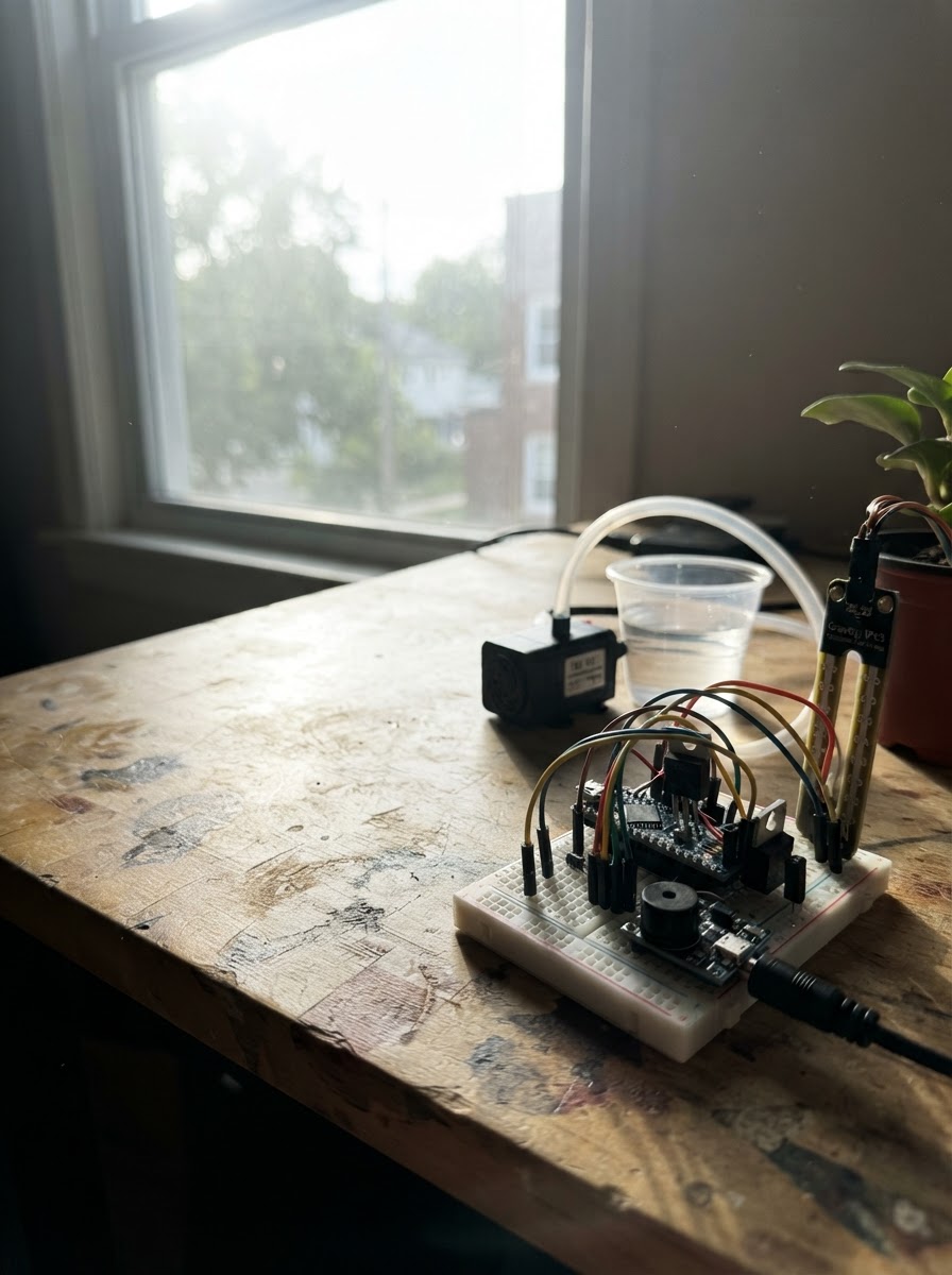
This automatic plant watering system monitors soil moisture with a capacitive sensor and triggers a 12V water pump when the soil dries out. The ESP32 microcontroller reads moisture levels, controls the pump via a MOSFET switch, and sounds an alert buzzer when watering begins. Builders will receive a complete wiring diagram, parts list, firmware with calibration guidance, and step-by-step assembly instructions covering water line preparation, sensor and buzzer hookup, pump switching circuit, flyback diode protection, power supply verification, and initial moisture calibration.
The system uses an MP1584 buck converter to safely step down 12V to ESP32 logic levels, a logic-level MOSFET to switch the pump on demand, and a 1N4007 diode to protect against inductive kickback. Assembly follows a logical sequence from power isolation through electrical testing to final calibration, ensuring safe handling of both water and high-voltage components.
Wiring diagram

Gather all the parts
Assemble it in 6 steps
1. 断电并准备水路
先不要连接 12V 适配器。将 pump_1 放入水箱,出水管固定在花盆土表面上方,避免水倒流到电子元件。
- 先用清水短暂测试水泵和管路是否通畅。
- 让水泵始终浸在水中再运行。
- 电子元件、ESP32 和适配器必须放在远离漏水的位置。
- 水泵不得干转。
2. 连接湿度传感器和蜂鸣器
soil_sensor_1 的 VCC 接 ESP32 3V3、GND 接 ESP32 GND、AOUT 接 GPIO34。buzzer_1 的 GND 接 GND,SIGNAL 接 GPIO25;若你的蜂鸣器模块另有 VCC 引脚,则接 ESP32 3V3。
- 只将传感器探头部分插入土中,连接端保持干燥。
- GPIO34 是仅输入的模拟脚,正适合传感器输出。
- 传感器 AOUT 不可接 5V;本设计使用 3.3V 供电,确保 ESP32 模拟输入安全。
3. 搭建水泵 MOSFET 开关
pump_1 的 PUMP+ 接 adapter_1 的 +12V;PUMP- 接 mosfet_1 的 DRAIN;mosfet_1 的 SOURCE 接公共 GND。gate_resistor_1(100Ω)串联在 GPIO26 与 mosfet_1 的 GATE 之间。gate_pulldown_1(10kΩ)一端接 GATE、另一端接公共 GND。
- IRLZ44N 面向你、引脚朝下时通常为 GATE、DRAIN、SOURCE;仍请以所购器件的数据手册/丝印为准。
- 把 12V 适配器负极、MOSFET SOURCE、ESP32 GND 接到同一个公共地。
- 绝不可把水泵接到 ESP32 GPIO 或 3.3V 引脚。
- 确认 MOSFET 引脚顺序后才通电,接反可能损坏器件。
4. 安装续流二极管
flyback_diode_1 并联在 pump_1 两端:有色环的 Cathode 接泵 PUMP+ / +12V;无环的 Anode 接泵 PUMP- / MOSFET DRAIN。
- 二极管应尽量靠近水泵接线端安装。
- 二极管极性不能反:有色环的一端必须接 +12V。接反会造成电源短路。
5. 连接降压供电并检查电压
adapter_1 的 +12V 接 buck_1 VIN,负极接 buck_1 GND。先在未接 ESP32 时给适配器通电,用万用表调节 buck_1,使 VOUT 对 GND 为稳定的 5.0V;断电后再把 VOUT 接 ESP32 VIN、GND 接公共 GND。
- ESP32 的 USB 连接也可用于上传和串口查看;不要在 USB 供电与 buck 输出接入 VIN 的情况下随意改线。
- 确认所有地线已经相连后再接上电源。
- MP1584 输出必须先调到 5.0V;高于 5V 可能损坏 ESP32 VIN 供电部分。
- 不要将 12V 直接接入 ESP32 的 VIN 或 3V3。
6. 首次上电与湿度校准
通电后用 Schematik 的 Deploy 按钮烧录。观察串口输出的 Soil raw 值:记录探头在干土/空气中的值并替换 RAW_DRY,记录在充分湿润土壤中的值并替换 RAW_WET;保持 RAW_DRY 大于 RAW_WET。
- 程序默认每 60 秒采样一次;湿度低于 20% 时蜂鸣 3 秒并让水泵运行 5 秒。
- 每次浇水后程序至少等待 5 分钟才允许下一次启动水泵,避免过度浇水。
- 首次测试时把出水管对准容器而非花盆,先确认水泵工作时间和流量合适。
Review all connections
1. Connections between "soil_sensor_1" and "ESP32"
2. Connections between "buzzer_1" and "ESP32"
3. Connections between "adapter_1" and "ESP32"
4. Connections between "buck_1" and "ESP32"
5. Connections between "pump_1" and "ESP32"
6. Connections between "mosfet_1" and "ESP32"
7. Connections between "flyback_diode_1" and "ESP32"
8. Connections between "gate_resistor_1" and "ESP32"
9. Connections between "gate_pulldown_1" and "ESP32"
Deploy the firmware
#include <Arduino.h>


// Forward declarations
int readSoilRaw();
int rawToPercent(int raw);
void startAlert(unsigned long now);
void stopAlert();
void startPump(unsigned long now);
void stopPump(unsigned long now);

constexpr int SOIL_PIN = 34;
constexpr int BUZZER_PIN = 25;
constexpr int PUMP_PIN = 26;

// Calibrate these two readings for your own soil and sensor.
// RAW_DRY: probe in air/dry soil; RAW_WET: probe in fully wet soil.
constexpr int RAW_DRY = 3000;
constexpr int RAW_WET = 1500;
constexpr int DRY_THRESHOLD_PERCENT = 20;
constexpr unsigned long SAMPLE_INTERVAL_MS = 60000UL;
constexpr unsigned long PUMP_DURATION_MS = 5000UL;
constexpr unsigned long PUMP_COOLDOWN_MS = 300000UL;
constexpr unsigned long BUZZER_TOGGLE_MS = 150UL;
constexpr unsigned long ALERT_DURATION_MS = 3000UL;

unsigned long lastSampleMs = 0;
unsigned long pumpStartedMs = 0;
unsigned long lastPumpStoppedMs = 0;
unsigned long alertStartedMs = 0;
unsigned long lastBuzzerToggleMs = 0;
bool pumpRunning = false;
bool alertActive = false;
bool buzzerOn = false;

int readSoilRaw() {
  long total = 0;
  for (int i = 0; i < 16; ++i) {
    total += analogRead(SOIL_PIN);
    delay(5);
  }
  return total / 16;
}

int rawToPercent(int raw) {
  const long numerator = static_cast<long>(RAW_DRY - raw) * 100L;
  const long denominator = RAW_DRY - RAW_WET;
  if (denominator == 0) return 0;
  return constrain(static_cast<int>(numerator / denominator), 0, 100);
}

void startAlert(unsigned long now) {
  alertActive = true;
  alertStartedMs = now;
  lastBuzzerToggleMs = now;
  buzzerOn = true;
  digitalWrite(BUZZER_PIN, HIGH);
}

void stopAlert() {
  alertActive = false;
  buzzerOn = false;
  digitalWrite(BUZZER_PIN, LOW);
}

void startPump(unsigned long now) {
  pumpRunning = true;
  pumpStartedMs = now;
  digitalWrite(PUMP_PIN, HIGH);
  Serial.println("Pump ON");
}

void stopPump(unsigned long now) {
  pumpRunning = false;
  lastPumpStoppedMs = now;
  digitalWrite(PUMP_PIN, LOW);
  Serial.println("Pump OFF");
}

void setup() {
  Serial.begin(115200);
  analogReadResolution(12);
  pinMode(BUZZER_PIN, OUTPUT);
  pinMode(PUMP_PIN, OUTPUT);
  digitalWrite(BUZZER_PIN, LOW);
  digitalWrite(PUMP_PIN, LOW);
  delay(200);
  lastSampleMs = millis() - SAMPLE_INTERVAL_MS;
  Serial.println("Soil watering controller ready");
}

void loop() {
  const unsigned long now = millis();

  if (pumpRunning && now - pumpStartedMs >= PUMP_DURATION_MS) {
    stopPump(now);
  }

  if (alertActive) {
    if (now - alertStartedMs >= ALERT_DURATION_MS) {
      stopAlert();
    } else if (now - lastBuzzerToggleMs >= BUZZER_TOGGLE_MS) {
      lastBuzzerToggleMs = now;
      buzzerOn = !buzzerOn;
      digitalWrite(BUZZER_PIN, buzzerOn ? HIGH : LOW);
    }
  }

  if (now - lastSampleMs < SAMPLE_INTERVAL_MS) return;
  lastSampleMs = now;

  const int raw = readSoilRaw();
  const int moisture = rawToPercent(raw);
  Serial.printf("Soil raw=%d, moisture=%d%%\n", raw, moisture);

  if (moisture < DRY_THRESHOLD_PERCENT) {
    Serial.println("Soil is below 20%: watering request");
    startAlert(now);
    if (!pumpRunning && now - lastPumpStoppedMs >= PUMP_COOLDOWN_MS) {
      startPump(now);
    } else {
      Serial.println("Pump cooldown active; warning only");
    }
  }
}
Remix this project
Make it yours in one click
Open a full copy of this project in your own Schematik workspace — diagram, code, parts, and assembly steps included. Swap the sensor, add features, or redesign the whole thing with AI. The author's original stays untouched.