Community project
Versi Yang Anda Susun Sudah Sangat Lengkap Namun
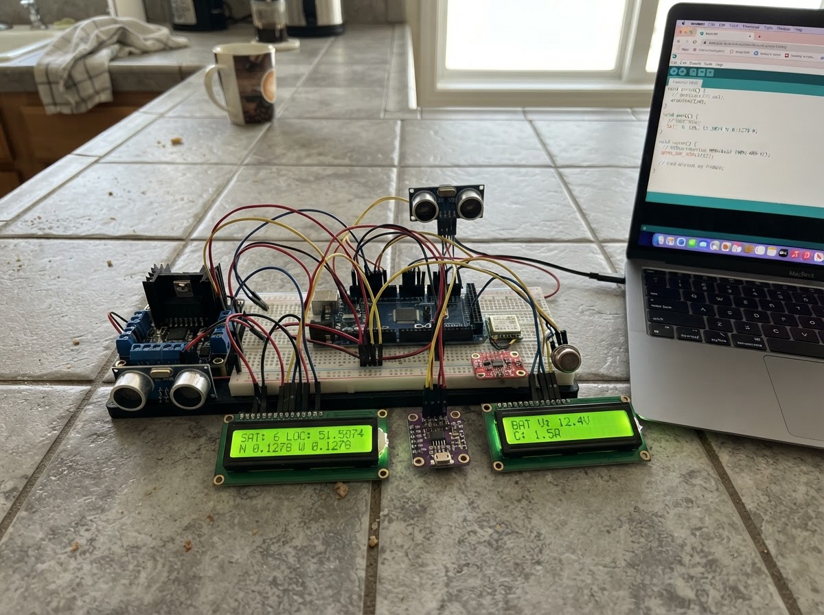
This guide builds a comprehensive Arduino-based mobile robot platform with 4WD drive capability, environmental sensing, and GPS navigation. The robot integrates motor control via the IBT-2 H-bridge driver, obstacle detection with ultrasonic ranging, thermal imaging with the MLX90614, motion tracking via the MPU-6050 IMU, and wireless Bluetooth control. Power comes from a protected 3S Li-ion battery pack with current monitoring through the INA219 sensor.
Makers will receive a complete wiring diagram showing all 20+ connections, a detailed parts list with pinout specifications, the full Arduino firmware with motor control and sensor integration routines, and step-by-step assembly instructions covering safe power distribution, 4WD drivetrain installation, and sensor mounting. The guide includes code for autonomous navigation modes, manual Bluetooth control, real-time data logging to microSD, and dual LCD display output for navigation and environmental parameters.
Wiring diagram

Gather all the parts
Assemble it in 3 steps
1. Rakit catu daya aman
Susun enam sel 18650 sebagai 3S2P memakai holder/pack yang sesuai dan BMS 3S 20 A. Pasang fuse blade 10 A, saklar utama, dan emergency stop secara seri pada jalur positif sebelum distribusi. Atur LM2596 logic_regulator tepat 5,0 V dengan multimeter sebelum Arduino Mega dan modul apa pun dipasang.
- Semua ground sistem, termasuk kedua BTS7960 dan Arduino, wajib tersambung bersama.
- Gunakan kabel daya motor yang lebih tebal daripada kabel sinyal.
- Jangan hubungkan charger 12,6 V ke keluaran pack tanpa mengikuti terminal BMS yang benar.
- Jangan pernah mengatur LM2596 saat Arduino/modul masih tersambung.
2. Pasang penggerak 4WD
Pasang motor kiri depan dan belakang paralel pada keluaran driver kiri; motor kanan depan dan belakang paralel pada keluaran driver kanan. Hubungkan suplai motor 3S setelah fuse/saklar/emergency stop ke B+ dan B− masing-masing driver. Hubungkan sinyal Mega sesuai tabel wiring proyek.
- Uji roda terangkat dari lantai terlebih dahulu; tukar M+ dan M− pada satu sisi jika arah maju terbalik.
- BTS7960 bukan pengganti fuse. Pastikan kabel dan konektor mampu menahan arus stall motor.
- Jangan menghubungkan motor langsung ke pin Arduino.
3. Pasang sensor, antarmuka, dan layar
Hubungkan semua modul I²C ke SDA D20 dan SCL D21; LCD navigasi memakai 0x27 dan LCD lingkungan 0x26. Hubungkan GPS ke Serial1, HC-05 ke Serial2, MicroSD ke SPI D50–D53, serta sensor analog ke A0/A1. Pasang servo dan HC-SR04 di bagian depan.
- Arahkan antena GPS ke atas dan jauhkan dari BTS7960.
- Pasang resistor 220 Ω seri pada setiap LED.
- INA219 standar tidak aman untuk arus total motor; gunakan hanya untuk cabang logika atau sensor arus ber-rating tinggi khusus jalur motor.
- Modul MQ perlu pemanasan dan kalibrasi di udara bersih sebelum pembacaan dipakai sebagai ambang bahaya.
Review all connections
1. Connections between "battery_pack" and "Arduino"
2. Connections between "logic_regulator" and "Arduino"
3. Connections between "motor_driver_left" and "Arduino"
4. Connections between "motor_driver_right" and "Arduino"
5. Connections between "ultrasonic" and "Arduino"
6. Connections between "servo_scan" and "Arduino"
7. Connections between "gps" and "Arduino"
8. Connections between "bluetooth" and "Arduino"
9. Connections between "imu" and "Arduino"
10. Connections between "ir_temperature" and "Arduino"
11. Connections between "power_monitor" and "Arduino"
12. Connections between "lcd_navigation" and "Arduino"
13. Connections between "lcd_environment" and "Arduino"
14. Connections between "micro_sd" and "Arduino"
15. Connections between "gas_smoke" and "Arduino"
16. Connections between "gas_air" and "Arduino"
17. Connections between "obstacle_left" and "Arduino"
18. Connections between "obstacle_right" and "Arduino"
19. Connections between "line_left" and "Arduino"
20. Connections between "line_right" and "Arduino"
21. Connections between "mode_switch" and "Arduino"
22. Connections between "status_leds" and "Arduino"
23. Connections between "alarm_buzzer" and "Arduino"
Deploy the firmware
#include <Arduino.h>
#include <Wire.h>
#include <Servo.h>
#include <LiquidCrystal_I2C.h>
#include <TinyGPS++.h>
#include <Adafruit_MLX90614.h>
#include <Adafruit_INA219.h>
#include <SD.h>

#define LEFT_LPWM 6
#define RIGHT_RPWM 7
#define RIGHT_LPWM 8
#define ECHO_PIN 27
#define SERVO_PIN 9
#define MODE_PIN 44
#define FC_RIGHT 29
#define LINE_LEFT 30
#define LINE_RIGHT 31
#define MQ135_PIN 55
#define SD_CS 53
#define BUZZER 45


// Forward declarations
void drive(int l,int r);
void stopDrive();
long distanceCm();
void manualControl();
void autonomous();

const uint8_t LEFT_RPWM=5, LEFT_LPWM=6, RIGHT_RPWM=7, RIGHT_LPWM=8;
const uint8_t LEFT_REN=22, LEFT_LEN=23, RIGHT_REN=24, RIGHT_LEN=25;
const uint8_t TRIG_PIN=26, ECHO_PIN=27, SERVO_PIN=9, MODE_PIN=44;
const uint8_t FC_LEFT=28, FC_RIGHT=29, LINE_LEFT=30, LINE_RIGHT=31;
const uint8_t MQ2_PIN=A0, MQ135_PIN=A1, SD_CS=53;
const uint8_t LED_GREEN=10, LED_RED=11, LED_BLUE=12, LED_YELLOW=13, LED_WHITE=46, BUZZER=45;
LiquidCrystal_I2C lcdNav(0x27,16,2), lcdEnv(0x26,16,2);
TinyGPSPlus gps; Adafruit_MLX90614 mlx; Adafruit_INA219 ina219; Servo scanServo;
bool sdOK=false; unsigned long lastDisplay=0,lastLog=0;
void drive(int l,int r){digitalWrite(LEFT_REN,HIGH);digitalWrite(LEFT_LEN,HIGH);digitalWrite(RIGHT_REN,HIGH);digitalWrite(RIGHT_LEN,HIGH);analogWrite(LEFT_RPWM,l>0?l:0);analogWrite(LEFT_LPWM,l<0?-l:0);analogWrite(RIGHT_RPWM,r>0?r:0);analogWrite(RIGHT_LPWM,r<0?-r:0);}
void stopDrive(){drive(0,0);}
long distanceCm(){digitalWrite(TRIG_PIN,LOW);delayMicroseconds(2);digitalWrite(TRIG_PIN,HIGH);delayMicroseconds(10);digitalWrite(TRIG_PIN,LOW);unsigned long t=pulseIn(ECHO_PIN,HIGH,25000);return t?t/58:400;}
void manualControl(){while(Serial2.available()){char c=Serial2.read(); if(c=='F')drive(170,170); else if(c=='B')drive(-170,-170); else if(c=='L')drive(-150,150); else if(c=='R')drive(150,-150); else if(c=='S')stopDrive();}}
void autonomous(){long d=distanceCm(); bool blocked=(d<25)||(digitalRead(FC_LEFT)==LOW)||(digitalRead(FC_RIGHT)==LOW); if(blocked){stopDrive();digitalWrite(LED_RED,HIGH);digitalWrite(BUZZER,HIGH);delay(180);drive(-140,-140);delay(280);drive(150,-150);delay(350);stopDrive();}else{digitalWrite(LED_RED,LOW);digitalWrite(BUZZER,LOW); bool l=digitalRead(LINE_LEFT)==LOW,r=digitalRead(LINE_RIGHT)==LOW; if(l&&!r)drive(100,180); else if(r&&!l)drive(180,100); else drive(155,155);}}
void setup(){pinMode(TRIG_PIN,OUTPUT);pinMode(ECHO_PIN,INPUT);pinMode(MODE_PIN,INPUT_PULLUP);pinMode(FC_LEFT,INPUT);pinMode(FC_RIGHT,INPUT);pinMode(LINE_LEFT,INPUT);pinMode(LINE_RIGHT,INPUT);pinMode(BUZZER,OUTPUT);for(uint8_t p: {LED_GREEN,LED_RED,LED_BLUE,LED_YELLOW,LED_WHITE})pinMode(p,OUTPUT);Serial.begin(115200);Serial1.begin(9600);Serial2.begin(9600);Wire.begin();lcdNav.init();lcdNav.backlight();lcdEnv.init();lcdEnv.backlight();scanServo.attach(SERVO_PIN);scanServo.write(90);mlx.begin();ina219.begin();sdOK=SD.begin(SD_CS);digitalWrite(LED_GREEN,HIGH);}
void loop(){while(Serial1.available())gps.encode(Serial1.read());bool autonomousMode=digitalRead(MODE_PIN)==LOW;if(autonomousMode)autonomous();else manualControl();if(millis()-lastDisplay>500){lastDisplay=millis();float obj=mlx.readObjectTempC();float v=ina219.getBusVoltage_V();int mq2=analogRead(MQ2_PIN),mq135=analogRead(MQ135_PIN);lcdNav.setCursor(0,0);lcdNav.print(autonomousMode?"AUTO ":"MANUAL");lcdNav.print(" D:");lcdNav.print(distanceCm());lcdNav.print(" ");lcdNav.setCursor(0,1);if(gps.location.isValid()){lcdNav.print(gps.location.lat(),4);lcdNav.print(",");lcdNav.print(gps.location.lng(),4);}else lcdNav.print("GPS searching...");lcdEnv.setCursor(0,0);lcdEnv.print("T:");lcdEnv.print(obj,1);lcdEnv.print("C V:");lcdEnv.print(v,1);lcdEnv.setCursor(0,1);lcdEnv.print("M2:");lcdEnv.print(mq2);lcdEnv.print(" M135:");lcdEnv.print(mq135);digitalWrite(LED_BLUE,gps.location.isValid());digitalWrite(LED_YELLOW,sdOK);digitalWrite(LED_WHITE,obj>45);if(sdOK&&millis()-lastLog>5000){lastLog=millis();File f=SD.open("arv.csv",FILE_WRITE);if(f){f.print(millis());f.print(',');f.print(autonomousMode);f.print(',');f.print(distanceCm());f.print(',');f.print(obj);f.print(',');f.print(mq2);f.print(',');f.println(mq135);f.close();}}}}
Remix this project
Make it yours in one click
Open a full copy of this project in your own Schematik workspace — diagram, code, parts, and assembly steps included. Swap the sensor, add features, or redesign the whole thing with AI. The author's original stays untouched.
Related projects
Necesito Hacer Un Circuito De Un Oxiometro Con
Arduino · September 25, 2026MARIA PAULA LAMBOGLIA VARGAS
Laser Harp Instrument
Arduino · September 25, 2026juliasualoka2
Três Sensores de Luz
Arduino · September 25, 2026arthur.brazil