On this page
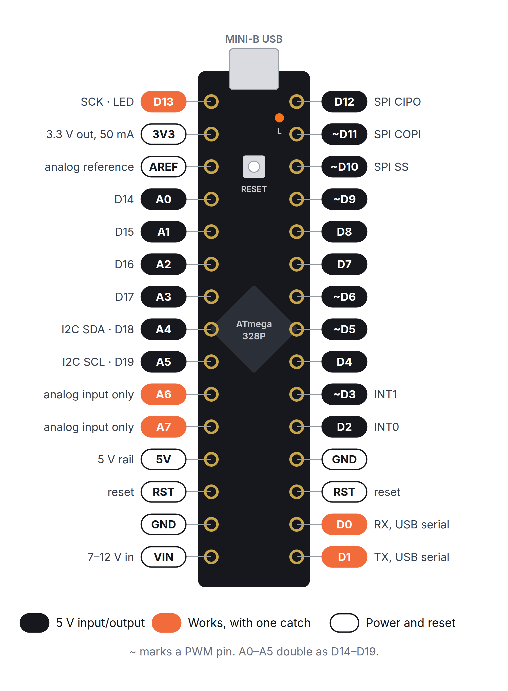
The classic Arduino Nano has 30 pins in two rows of 15. Twenty-two of them are input/output pins: D0 to D13 and A0 to A7. Every signal pin works at 5 V.
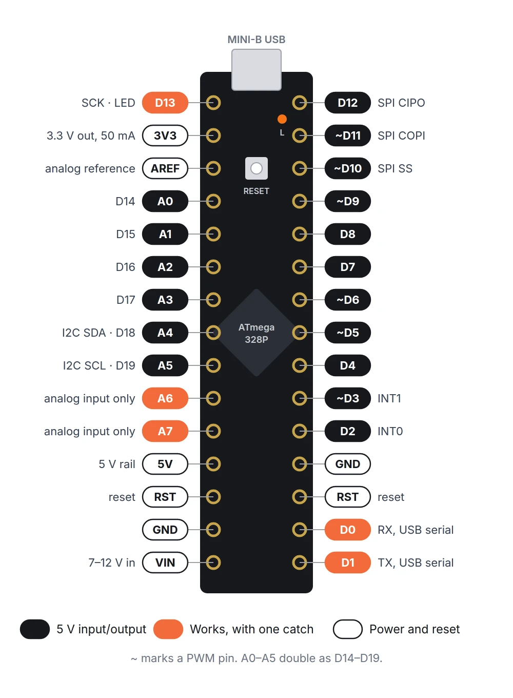
A6 and A7 are analog input only. The orange pins each have one catch, covered in pins to watch out for. Want it next to your breadboard? Open the full-size pinout PNG and print it.
Arduino Nano pin table
Hold the board face up with the USB port at the top. The Nano runs an ATmega328P at 16 MHz, with 32 KB of flash (2 KB of it taken by the bootloader), 2 KB of SRAM and 1 KB of EEPROM.
Left header, top to bottom
| Pin | Chip pin | What it does |
|---|---|---|
| D13 | PB5 | Digital, SPI SCK, built-in LED |
| 3V3 | 3.3 V out, 50 mA max | |
| AREF | Analog reference | |
| A0 | PC0 | Analog in, digital D14 |
| A1 | PC1 | Analog in, digital D15 |
| A2 | PC2 | Analog in, digital D16 |
| A3 | PC3 | Analog in, digital D17 |
| A4 | PC4 | Analog in, digital D18, I2C SDA |
| A5 | PC5 | Analog in, digital D19, I2C SCL |
| A6 | ADC6 | Analog in only |
| A7 | ADC7 | Analog in only |
| 5V | 5 V rail | |
| RESET | PC6 | Pull low to restart the sketch |
| GND | Ground | |
| VIN | 7 to 12 V in |
Right header, top to bottom
| Pin | Chip pin | What it does |
|---|---|---|
| D12 | PB4 | Digital, SPI CIPO |
| D11 | PB3 | Digital, PWM, SPI COPI |
| D10 | PB2 | Digital, PWM, SPI SS |
| D9 | PB1 | Digital, PWM |
| D8 | PB0 | Digital |
| D7 | PD7 | Digital |
| D6 | PD6 | Digital, PWM |
| D5 | PD5 | Digital, PWM |
| D4 | PD4 | Digital |
| D3 | PD3 | Digital, PWM, interrupt INT1 |
| D2 | PD2 | Digital, interrupt INT0 |
| GND | Ground | |
| RESET | PC6 | Pull low to restart the sketch |
| D0 / RX | PD0 | Digital, serial RX to USB |
| D1 / TX | PD1 | Digital, serial TX to USB |
Which pins do what
PWM pins
Six pins can do PWM, a fast on-off signal that dims LEDs and sets motor speed: D3, D5, D6, D9, D10 and D11. Each has a ~ next to its number on the board.
Set the level with analogWrite(pin, value), where value runs from 0 (off) to 255 (fully on). If the pin drives an LED, work out its resistor with what resistor to use for an LED.
Analog pins
The Nano has eight analog inputs, A0 to A7. analogRead() returns a 10-bit number from 0 to 1023 for 0 to 5 V, so each step is about 4.9 mV. To measure against a different top voltage, wire it to AREF and call analogReference().
A0 to A5 also work as ordinary digital pins, numbered D14 to D19. A6 and A7 only connect to the chip's analog-to-digital converter, so they can't.
I2C, SPI and serial
| Bus | Pins |
|---|---|
| I2C | A4 SDA, A5 SCL |
| SPI | D11 COPI, D12 CIPO, D13 SCK, D10 SS |
| Serial (UART) | D0 RX, D1 TX |
COPI and CIPO are the new names for MOSI and MISO. Any free digital pin can be an SPI chip select. D0 and D1 are wired to the board's FT232RL USB-to-serial chip, which is how the Serial Monitor reaches your computer.
Interrupt pins
An interrupt runs a function the moment a pin changes, even halfway through loop(). The Nano has two external interrupt pins: D2 (INT0) and D3 (INT1).
attachInterrupt(digitalPinToInterrupt(2), onPress, FALLING);
Power pins and current limits
| Pin | What it does |
|---|---|
| VIN | 7 to 12 V in, through the onboard regulator |
| 5V | 5 V rail: from USB, or from the regulator when you use VIN |
| 3V3 | 3.3 V out, 50 mA max |
| GND | Ground, two pins |
| RESET | Pull low to restart the sketch, two pins |
There is no barrel jack. Power comes from the Mini-B USB port, VIN, or a regulated 5 V supply on the 5V pin.
Three limits keep the chip alive:
- 20 mA per I/O pin. That is Arduino's rating for each pin.
- 40 mA per pin is the ATmega328P's absolute maximum, with 200 mA through its VCC and GND pins. Damage can start there. It is not a working value.
- 5.5 V on any signal pin. The datasheet limit is the supply voltage plus 0.5 V. Never feed VIN-level voltages into a signal pin.
Pins to watch out for
- D0 and D1. These carry the USB serial link. Anything wired to them can make uploads fail and interfere with the Serial Monitor. Use them last, and unplug them while you upload.
- D13. The built-in LED and its resistor sit on this pin. With
INPUT_PULLUPit floats at about 1.7 V and readsLOW. To use D13 as an input, set it toINPUTand add an external pull-down resistor. - A6 and A7. Analog input only.
digitalRead(),digitalWrite()andINPUT_PULLUPdon't work on them. - D5 and D6. They share a timer with
millis()anddelay(). Their PWM can run higher than you set it, andanalogWrite(pin, 0)may not switch them fully off.
Each digital pin has an internal pull-up of 20 to 50 kΩ. pinMode(pin, INPUT_PULLUP) turns it on, so a button only needs a wire to GND.
Arduino Nano vs Uno pins
The Nano and the Arduino Uno R3 use the same chip, the ATmega328P. A sketch written for one runs on the other with the same pin numbers.
| Nano | Uno R3 | |
|---|---|---|
| Digital pins | 14 | 14 |
| PWM pins | 6 | 6 |
| Analog inputs | 8 | 6 |
| Logic level | 5 V | 5 V |
| Current per pin | 20 mA | 20 mA |
| USB | Mini-B | USB-B |
| Barrel jack | No | Yes |
| Size | 45 × 18 mm | 68.6 × 53.4 mm |
| Weight | 7 g | 25 g |
The Nano adds A6 and A7 and comes with pin headers that plug straight into a breadboard.
Other Nano boards have different pinouts
The Nano name now covers several boards. Check the chip printed on yours before you wire anything.
- Nano Every: ATmega4809, 5 V. Arduino calls the pinout the same as the classic Nano, but it has 5 PWM pins and every digital pin can take an interrupt.
- Nano ESP32: ESP32-S3 in a u-blox NORA-W106 module, 3.3 V logic. A 5 V signal will damage it, and the 5V pin is replaced by VBUS, which only has power on USB. See Arduino's Nano ESP32 page and 3.3 V vs 5 V level shifting.
- Nano RP2040 Connect: Raspberry Pi RP2040, 3.3 V logic, 12 mA per pin. Arduino lists it as end of life.
Builds that use the Nano
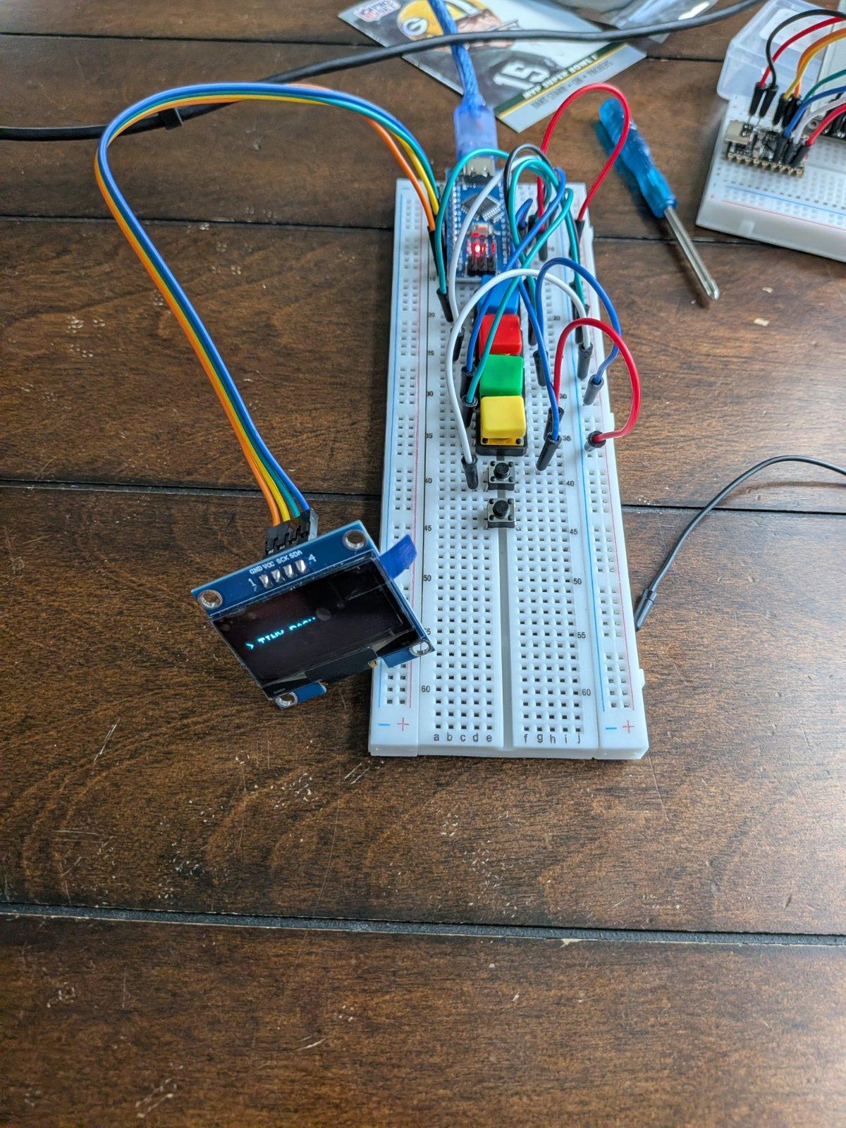
The 5-Button OLED Mini Game Deck by patelveer0712 puts Tetris, Snake, Flappy Bird, Pong, Asteroids and Dash on a 1.3-inch 128 × 64 OLED. The screen sits on the I2C pins, SDA on A4 and clock on A5. Five buttons go from D2 to D6 down to GND, with no resistors, because the sketch turns on the built-in pull-ups.
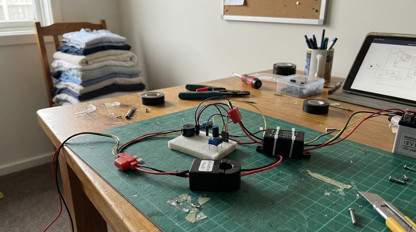
The Motorcycle Indicator Timeout Alert by Tony Pearce beeps when a turn signal has been left on too long. A clamp-on Hall effect current sensor on A1 notices the indicator is on, a knob on A0 sets the timeout from 10 to 120 seconds and a buzzer on D9 sounds. A waterproof converter turns the bike battery into 5 V and feeds the Nano's 5V pin, not VIN.
More Nano and Uno builds are in the Arduino projects.
Try it without a board
The Schematik simulator runs Arduino Uno, Nano and Mega sketches in the browser. This one is a laser tripwire on an Uno: drag the light sensor down and the Serial Monitor prints "Intruder detected".
To start your own, open Schematik and paste:
Arduino Nano with a button on D2 and an LED on D9 that fades in when I press it.
FAQ
How many pins does the Arduino Nano have?
- Fourteen are digital (D0 to D13) and eight are analog inputs (A0 to A7). The other eight are 5V, 3V3, VIN, AREF, two GND and two RESET.
Which pins are PWM on the Arduino Nano?
D3, D5, D6, D9, D10 and D11. They are marked ~ on the board.
Which pins are I2C on the Arduino Nano?
A4 is SDA and A5 is SCL.
Can I use A6 and A7 as digital pins?
No. They only connect to the analog-to-digital converter. If you need more digital pins, A0 to A5 work as D14 to D19.
Keep building from here
Jump into a step-by-step build, or open Schematik and turn your own idea into code, wiring, and assembly instructions.
Related posts
What is I2C? How it works, ESP32 wiring and I2C vs SPI
I2C lets a screen and a motion sensor share the same 2 wires on an ESP32-S3. Here is how the addresses work, what one message looks like and when SPI is the better pick.
Pull-up and pull-down resistors: what they do and how to wire one
A button wired straight to a pin reads random presses. One 10kΩ resistor fixes it. Here is how pull-up and pull-down resistors work, and when the ESP32-S3's built-in ones are enough.
Logic level shifter: when an ESP32 needs one and how to wire it
Your ESP32 speaks 3.3V and some parts speak 5V. Here is how to tell when that matters, and the three ways to connect them safely: a divider, a buffer chip or a MOSFET shifter.