
On this page
A hair clip with a screen in it. It sits above your ear like a normal barrette, except it can say anything you want — your name, a joke, whatever you feel like that day.
The concept was pioneered by @meshtimes on Instagram. All the credit for the idea goes to her; this is a build guide so you can make your own.
Watch the full build on YouTube, or read on.
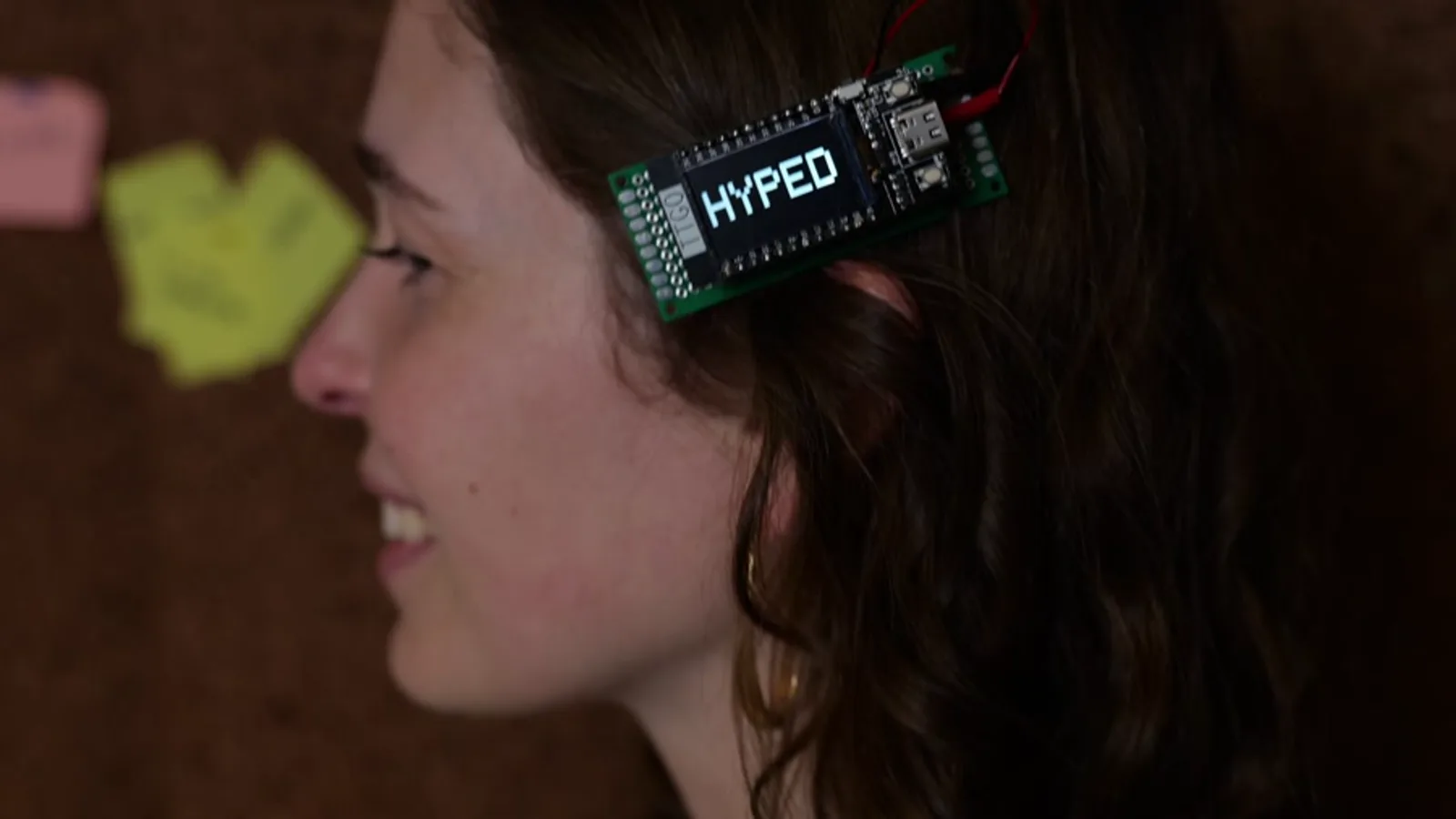
Why this is a good first project
Most wearables are a mess of small wires, and the display is usually the worst part — half a dozen connections that all have to land on the right pins before anything shows up.
This one skips that entirely. The brain is a LilyGo T-Display v1.1: an ESP32 with a 1.14-inch colour screen already soldered to it. The screen arrives done. The only thing you connect is the battery, and if you buy a LiPo with the right connector, even that is a plug rather than a solder joint.
Parts
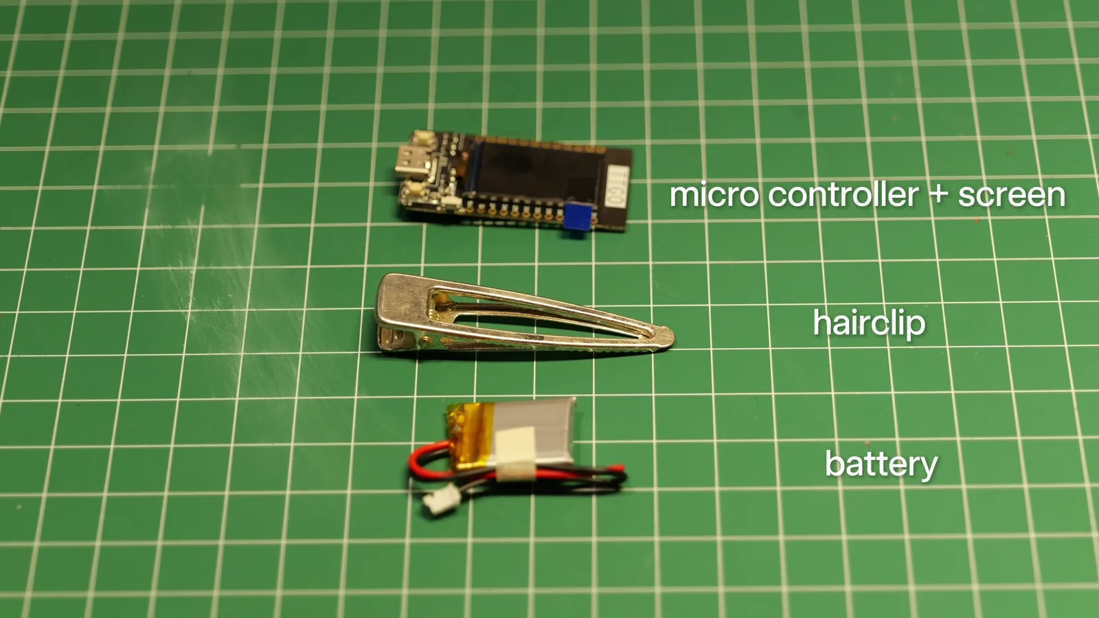
- LilyGo T-Display v1.1 — ESP32 with the 1.14-inch display built in. Direct from LilyGo · Amazon · AliExpress · Tindie
- 3.7 V LiPo, 400–450 mAh, with a Micro JST 1.25 mm 2-pin plug. The connector is the part that matters — see the warning below. Amazon (400 mAh, JST 1.25) · Rokland (JST 1.25, sold for LilyGo boards)
- A plain metal snap hair clip. Any basic barrette with a flat plate works; gold or silver is a look decision, not a technical one. Amazon
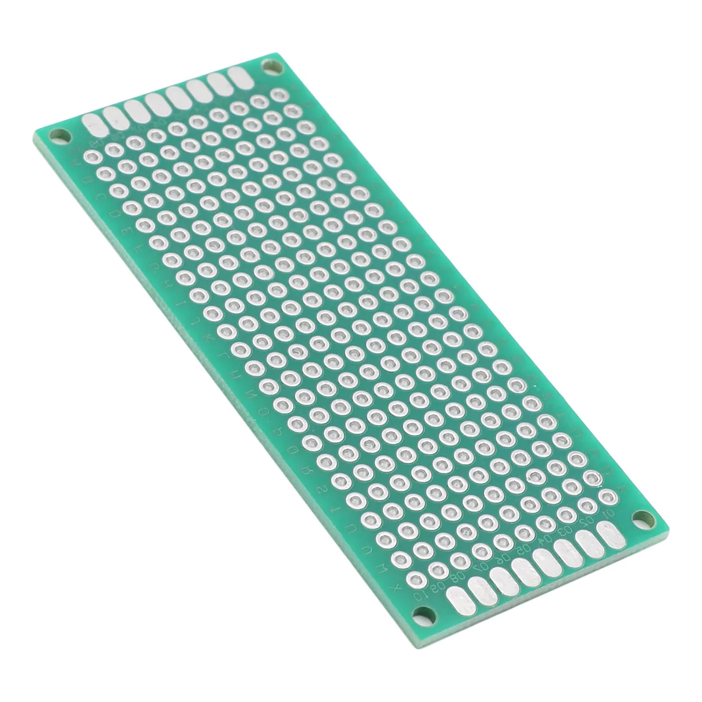
- A small piece of proto board, optional, for a tidier back. Adafruit prototyping boards · Amazon
- Super glue. Amazon
Get the connector right or you will be soldering. The T-Display takes a Micro JST 1.25 mm plug. Most hobby LiPo batteries — including nearly everything Adafruit sells — ship with JST-PH 2.0 mm, which is a different, larger connector and will not fit. Buying the 1.25 mm version is the single decision that removes all the soldering from this build.
Getting text on the screen
Open the starter project in Schematik. It arrives pre-loaded with the whole build described — the board, the pins, the message cycling, the sleep button — and writes the firmware for you. Then Deploy compiles it and flashes it over USB, straight from the browser, with no toolchain to install.
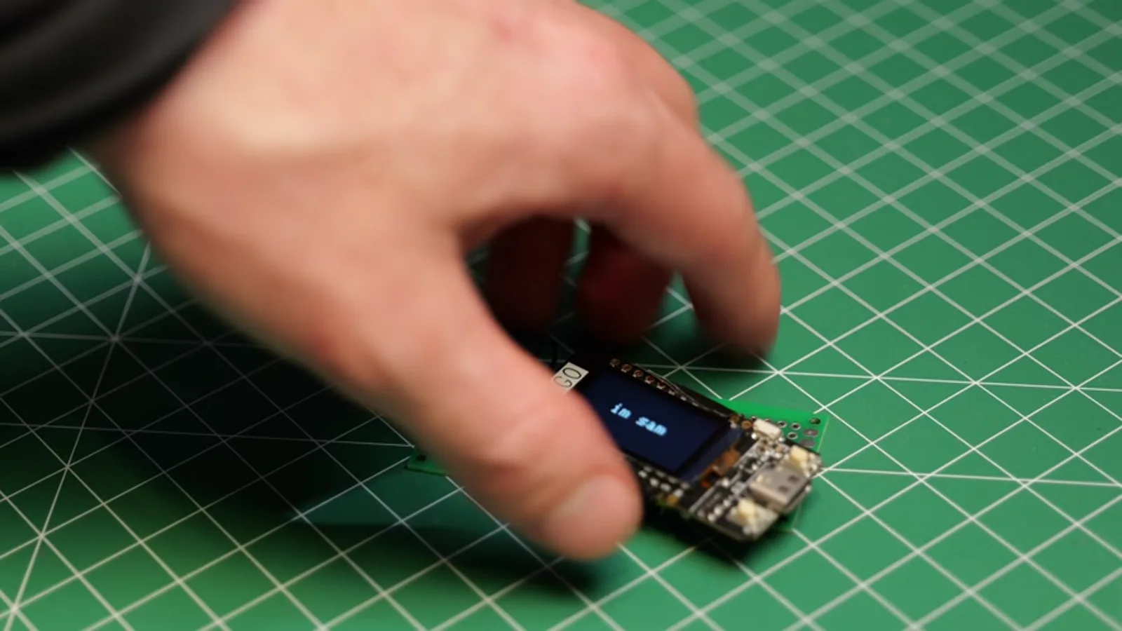
The sketch cycles through a short array of messages. Changing them is one line near the top:
const char *messages[] = {
  "Schematik Hairclip",
  "Schematik is great",
  "Like and Subscribe"
};
Put your own strings in and you have a personalised clip before you have soldered anything.
The board's two buttons are already wired inside it, so there is nothing to connect. The top one steps to the next message. The bottom one drops the board into deep sleep with the screen off, and wakes it again — that is your on/off switch once the thing is in your hair.
Message length changes how it looks. The screen is 240 pixels across and the sketch picks the largest text size that fits: five characters fill it at 64 pixels tall, thirteen still get 24, twenty get 16. Past twenty it would have to drop to 8 pixels, which nobody can read at arm's length, so it scrolls instead.
The two solder joints
Skip this if your battery already has a Micro JST 1.25 mm connector. Otherwise it is two joints: red to the positive pad, black to ground.
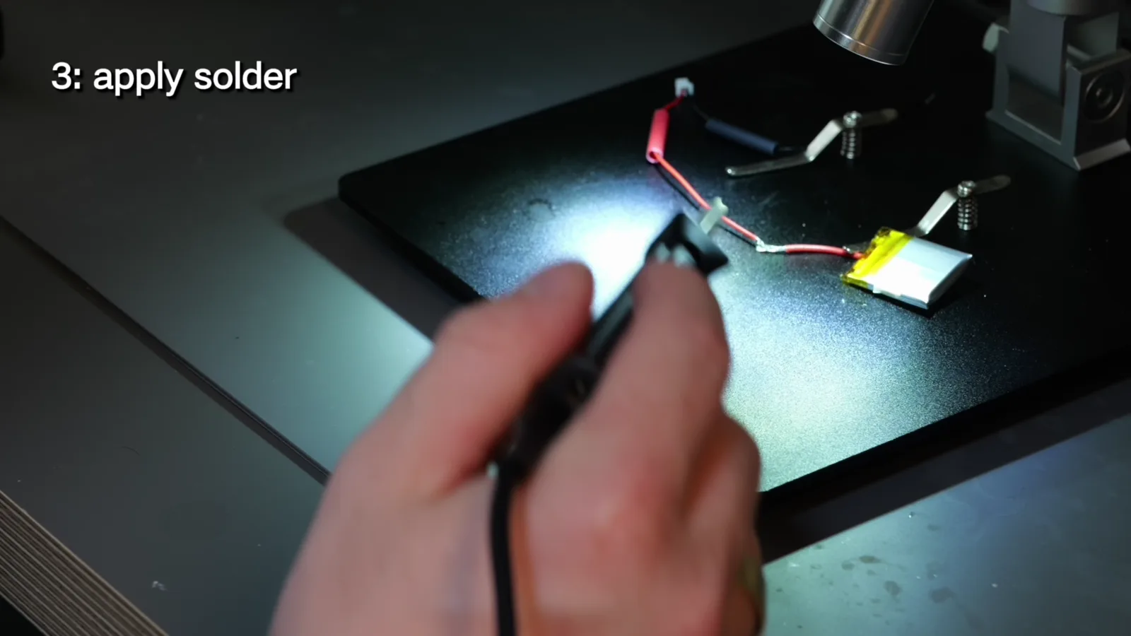
The order that works is strip, tin, then join — push the two conductors together first and heat them once, rather than trying to hold wire, iron and solder in three places at the same time.
Two things worth knowing before the iron is hot. A LiPo is not a AA — shorting the red and black together will ruin the cell and can make it vent, so strip and tin one wire at a time and never leave both bare ends loose. And check polarity against the silkscreen on the board rather than against a photo in a tutorial; connector wiring varies between batteries, and reversing it kills the board.
Assembly
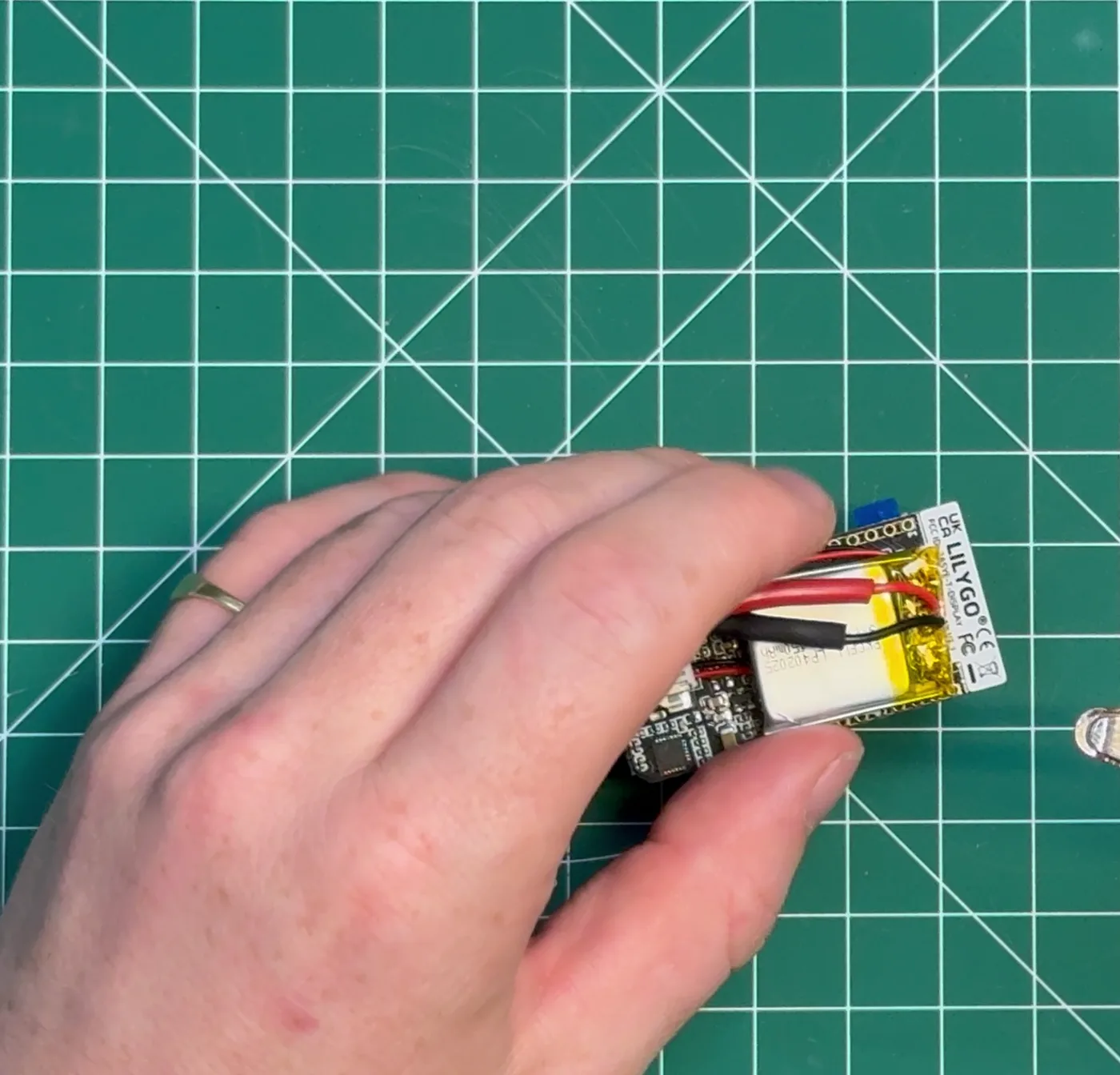
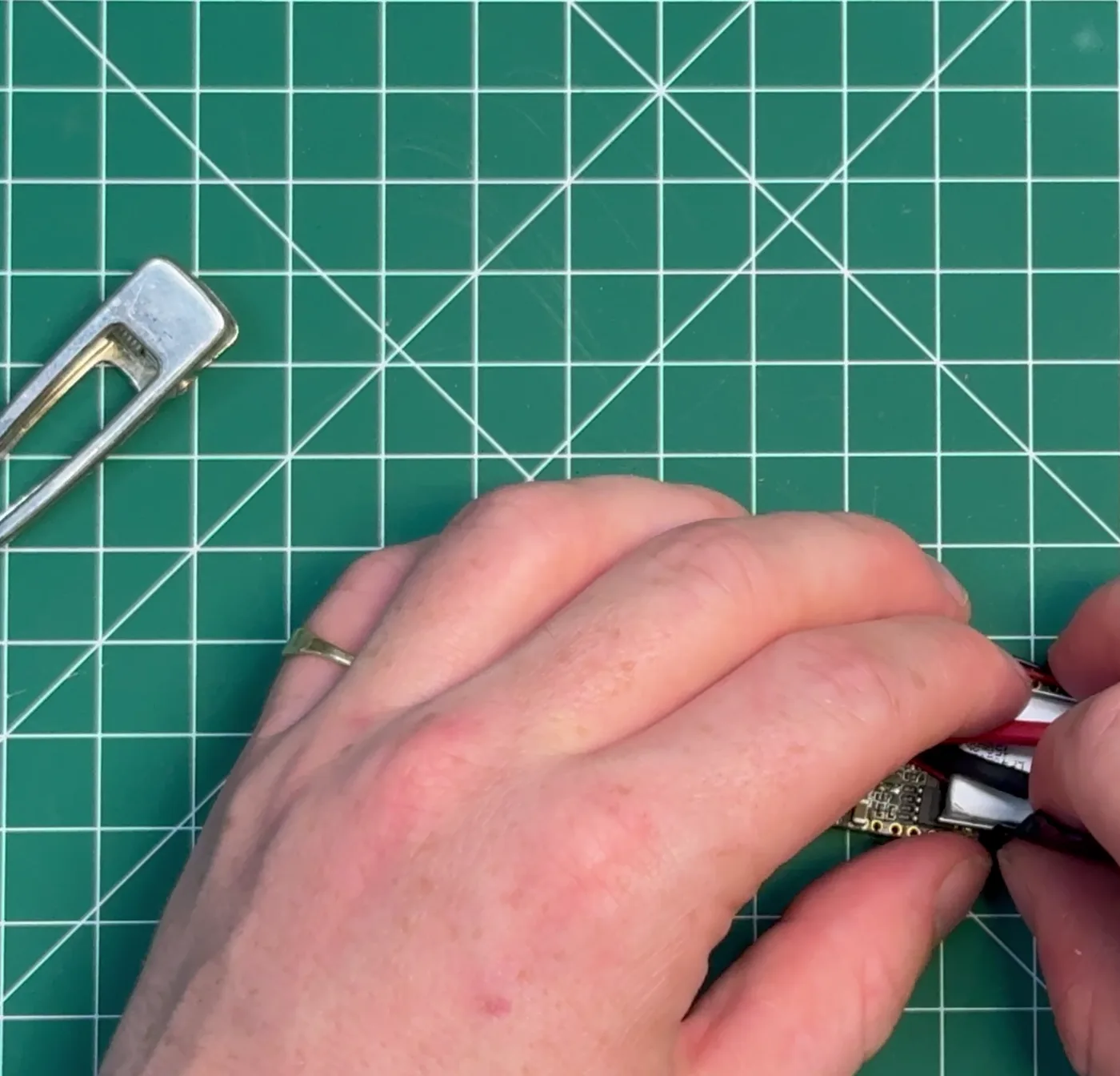
The battery sits flat against the back of the board, and the whole sandwich is what ends up in your hair. Tweezers help more than fingers here, because the JST plug is small and the wires are stiff enough to lever the battery back off if you push it in at an angle.
The part that actually took the longest
Not the electronics. The mounting.
Version one was taped together, and it did not hold. Tape fails here for a specific reason: the battery is heavy relative to the board, it hangs off the back, and every time you move your head it peels the tape a little further. It looks completely fine on the bench and falls apart within an hour of being worn. A rubber band held it together for a while, but that was a patch, not a finish.
So here is version two, which is the one worth copying.
Building it properly, on proto board
The idea is to give the board a rigid back. A small double-sided proto board does it, costs almost nothing, and means the clip has something solid to be glued to.
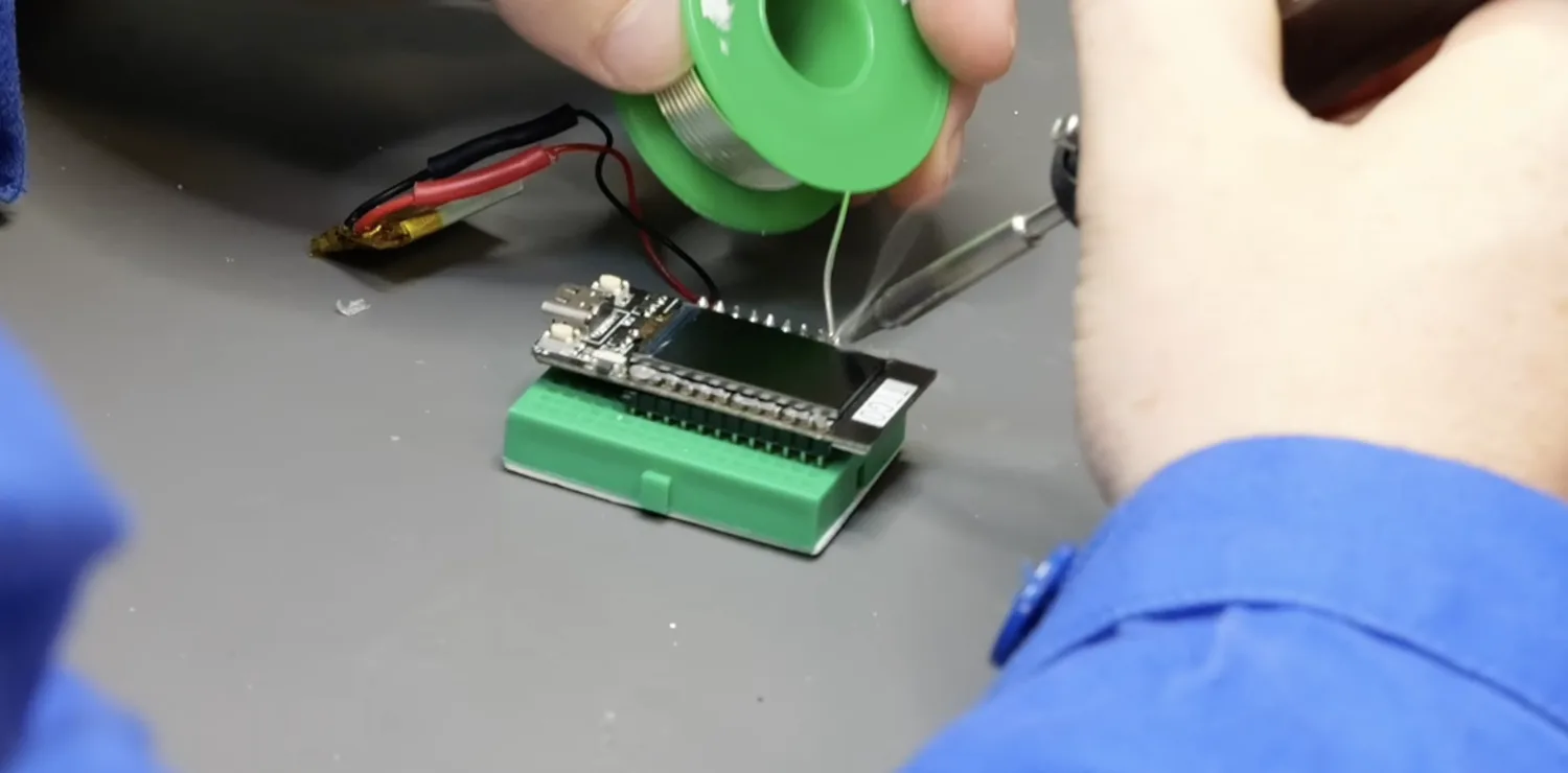
1. Solder header pins to the T-Display. Seat the pins in a breadboard first and drop the board on top — the breadboard holds everything square and level while you solder, which is most of the job. Tack one pin at each end, check the board is sitting flat, then do the rest.
2. Bring the battery through to the proto board. Run the battery wires to the proto board instead of straight to the display, and keep them short enough that nothing loops out past the edge of the clip. This is also the moment to sanity-check polarity one last time, because after this the joint is buried under the board.
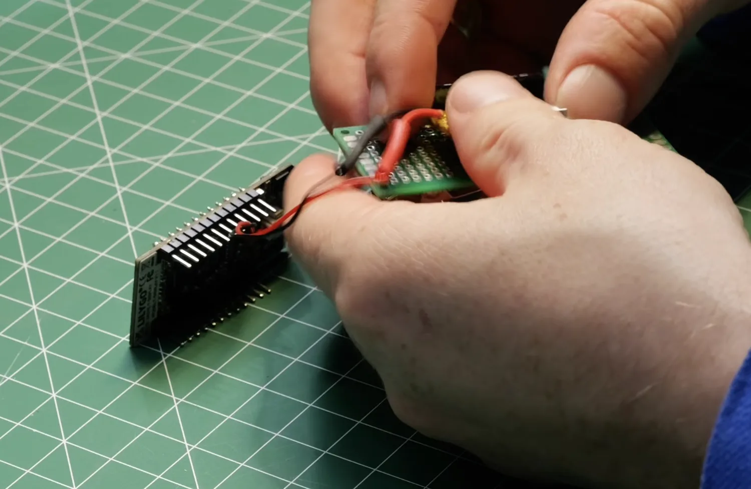
3. Glue the clip to the back. Super glue on the flat plate of the barrette, never the hinge — adhesive in the hinge means it will not open again, and you will have made a very expensive brooch. Let it cure fully before wearing it.
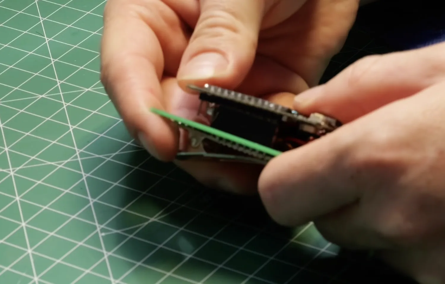
You end up with something you can pull apart later: the display unplugs from the headers, so the ESP32 goes back in the parts drawer when you are bored of it rather than being permanently glued to a hair accessory.
What I would change next
Two things, and both are about living with it rather than building it.
A real power switch. The bottom button sleeps the board, which is most of the way there, but it is still drawing a trickle and you have to remember to press it. A proper slide switch inline with the battery would cut the cell off completely — clip it in, flick it on, and know for certain it is off in your bag.
Wi-Fi for the text. Right now changing the message means plugging it into a laptop and redeploying. The ESP32 already has the radio; it just is not doing anything with it. A tiny web page served off the board, or a captive portal like the one in the ESP32-CAM setup portal guide, would let you retype it from your phone while it is still in your hair. That is the version I actually want.
Beyond that: if the text feels small once it is in your hair, shorten the message rather than hunting for a font setting — under about ten characters the sketch draws it as large as the screen allows. And runtime depends entirely on the cell; a 400–450 mAh LiPo gets you through an evening, with the screen doing nearly all of the draining.

If you build one, tag @meshtimes. It is her idea, and she deserves to see the versions it inspired. The other workshop builds are all in the same shape: one board, one evening, one specific thing to get working.
Keep building from here
Jump into a step-by-step build, or open Schematik and turn your own idea into code, wiring, and assembly instructions.
Related posts

How to Build an E-Ink Camera
A XIAO ESP32S3 Sense in a 3D-printed shell takes a photo and pushes the JPEG over ESP-NOW to an M5Stack PaperColor, where it lands on the e-ink screen. No router, no SD card, no phone.

New to Hardware? A Beginner ESP32 Guide for Your First Build
A beginner ESP32 hardware guide: what to buy first, how breadboards work, what pin labels mean, and what to check before powering your first build.
