Community project
Build Me Device That Uses Wifi To Scan
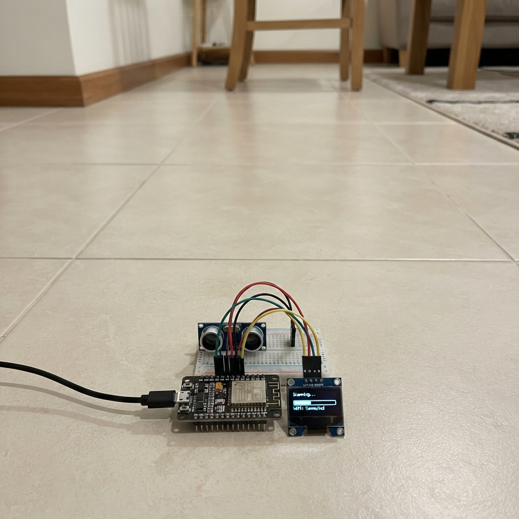
This handheld Wi-Fi scanner uses Channel State Information (CSI) to detect environmental changes and disturbances in radio propagation. Built around an ESP32 with a 2.8" capacitive touchscreen display, the device captures Wi-Fi channel measurements and correlates them with motion data from a 9-axis IMU to create a portable sensing platform. The scanner logs data to microSD card and runs on a rechargeable lithium battery with real-time fuel gauge monitoring.
This guide provides a complete wiring diagram, parts list, and step-by-step assembly instructions for integrating the display, sensors, buttons, and power system. Firmware is included to handle Wi-Fi CSI acquisition, IMU calibration, battery monitoring, and data logging. Builders will learn how to set up the radio interface, configure the touchscreen UI, and perform sensor calibration before taking measurements.
Wiring diagram

Gather all the parts
Assemble it in 6 steps
1. Prepare the radio board and antenna
Fit the ESP32-C6-DevKitC-1 in the handheld enclosure with its USB socket accessible. Press the 2.4 GHz u.FL antenna straight onto the board's tiny u.FL antenna socket until it clicks, then route the antenna away from the display and battery. This antenna carries the Wi-Fi signals used for the environmental measurements.
- Keep the antenna clear of metal screws and battery foil where possible; this improves repeatable readings.
- Do not power the board without an antenna fitted if you plan to use Wi-Fi heavily; the loose u.FL connector is delicate and pulling the cable sideways can tear it off.
2. Wire the display and microSD socket
Connect the display VCC wire to the 5V OUT/VIN supply rail (power), GND to GND (ground), SCK to GPIO18 (clock), MOSI to GPIO20 (display and card data), MISO to GPIO19 (card data back), TFT CS to GPIO21 (display select), D/C to GPIO10 (display control), RST to GPIO11 (display reset), TFT SDA to GPIO23 (touch data), TFT SCL to GPIO22 (touch clock), LITE to GPIO1 (backlight control), and SDCS to GPIO3 (microSD card select). Insert a formatted microSD card before closing the enclosure; the device records a CSI.csv file on it.
- Use short wires for GPIO18, GPIO19, and GPIO20 because they carry fast display and card signals.
- The display and microSD socket share SCK, MOSI, and MISO; that is intentional.
- Make sure VCC and GND are not swapped — swapped power can damage the screen. Do not force the microSD card; insert it with the contacts facing the socket contacts.
3. Wire the orientation and battery sensors
Connect BNO055 VIN to 3V3 (power), BNO055 GND to GND (ground), BNO055 SDA to GPIO23 (data), and BNO055 SCL to GPIO22 (clock). Connect MAX17048 VIN to 3V3 (power), MAX17048 GND to GND (ground), MAX17048 SDA to GPIO23 (data), MAX17048 SCL to GPIO22 (clock), and its BAT connection to the battery positive terminal (battery measurement). Mount the BNO055 flat and firmly in the case so it can tell when your hand is moving the scanner.
- Both small sensor boards share GPIO22 and GPIO23; this is intentional and lets them use the same two data wires.
- Keep the BNO055 away from magnets, speakers, and the boost converter for steadier compass readings.
- The MAX17048 BAT connection goes to the single-cell battery positive terminal, not the 5 V boosted output; connecting it to 5 V can damage the fuel gauge.
4. Add the two control buttons
For the SCAN button, connect one leg to GPIO6 (signal) and the other leg to GND (ground). For the CALIBRATE button, connect one leg to GPIO7 (signal) and the other leg to GND (ground). Place both buttons where your thumb can reach them without covering the antenna.
- On a four-leg pushbutton, use two legs on opposite sides of the small gap; legs on the same side are already connected together.
- SCAN starts or pauses logging. CALIBRATE records a quiet baseline while you hold the unit still for five seconds.
- Do not connect either button leg to 3V3; the firmware already supplies the safe internal pull-up connection.
5. Connect the rechargeable power system
Connect battery positive to the USB-C charge-and-boost module BAT+ terminal (battery power) and battery negative to BAT- (battery return). Connect the module 5V OUT terminal to the scanner's VIN/5V rail (power) and its GND terminal to the shared GND rail (ground). Put the battery and power board in separate insulated areas of the enclosure, then use the module's USB-C socket only for charging.
- Secure the battery so it cannot rub on sharp solder joints. Charge with the enclosure open the first time so you can check that nothing becomes hot.
- Never short the LiPo battery wires together — a shorted battery can rapidly overheat or catch fire. Do not charge a swollen, punctured, or hot battery.
6. Start and calibrate the scanner
Close the enclosure without pinching any wires. Power the unit, connect a phone to the temporary Wi-Fi network named CSI-Radar-Setup if it appears, and use its setup page to choose the nearby router that will provide the radio signal. Once the screen says Wi-Fi linked, stand in the intended location and hold the scanner still, then press CALIBRATE once and keep it still for five seconds. Press SCAN to start saving the channel-change measurements to the microSD card.
- Calibrate again after moving to a different room or changing the scanner's position; walls and furniture naturally change the Wi-Fi path.
- A high reading means the Wi-Fi path changed. It can be caused by a person, pet, movement, or the scanner itself moving.
- This is a motion and environmental-change indicator, not an identity detector and not a safe way to determine whether a person is behind a wall.
Review all connections
1. Connections between "tft_1" and "ESP32"
2. Connections between "imu_1" and "ESP32"
3. Connections between "gauge_1" and "ESP32"
4. Connections between "scan_button" and "ESP32"
5. Connections between "cal_button" and "ESP32"
6. Connections between "antenna_1" and "ESP32"
7. Connections between "battery_1" and "ESP32"
8. Connections between "power_1" and "ESP32"
Deploy the firmware
#include <Arduino.h>
#include <WiFi.h>
#include <WiFiManager.h>
#include <esp_wifi.h>
#include <SPI.h>
#include <SD.h>
#include <Wire.h>
#include <Adafruit_GFX.h>
#include <Adafruit_ILI9341.h>
#include <Adafruit_BNO055.h>
#include <Adafruit_Sensor.h>
#include <Adafruit_MAX17048.h>

// Handheld CSI environmental-sensing receiver for ESP32-C6.
// CSI is a measurement of received Wi-Fi channel change, not an object camera.

// Forward declarations
void csiCallback(void *, wifi_csi_info_t *info);
void enableCsi();
void drawStaticScreen();
void drawReadings();
void createLog();
void generateTraffic();
void updateImu();
void calibrateStep();
void updateMeasurement();
void handleButtons();

static constexpr int TFT_CS = 21;
static constexpr int TFT_DC = 10;
static constexpr int TFT_RST = 11;
static constexpr int TFT_BACKLIGHT = 1;
static constexpr int SD_CS = 3;
static constexpr int I2C_SDA = 23;
static constexpr int I2C_SCL = 22;
static constexpr int SCAN_BUTTON = 6;
static constexpr int CAL_BUTTON = 7;

Adafruit_ILI9341 tft(TFT_CS, TFT_DC, TFT_RST);
Adafruit_BNO055 bno(55, 0x28, &Wire);
Adafruit_MAX17048 gauge;
WiFiManager wifiManager;

volatile uint32_t csiSamples = 0;
volatile float latestAmplitude = 0.0f;
volatile int latestSubcarriers = 0;
float baselineAmplitude = 0.0f;
float disturbance = 0.0f;
float imuMotion = 0.0f;
bool calibrating = false;
bool sensing = true;
bool sdReady = false;
bool imuReady = false;
bool gaugeReady = false;
uint32_t calibrationStart = 0;
uint32_t calibrationCount = 0;
float calibrationSum = 0.0f;
uint32_t lastScreen = 0;
uint32_t lastTraffic = 0;
uint32_t lastLog = 0;
uint32_t lastButtons = 0;

void csiCallback(void *, wifi_csi_info_t *info) {
  if (info == nullptr || info->buf == nullptr || info->len < 2) return;
  const int8_t *iq = info->buf;
  uint32_t sum = 0;
  int pairs = info->len / 2;
  for (int i = 0; i < pairs; ++i) {
    int16_t iPart = iq[i * 2];
    int16_t qPart = iq[i * 2 + 1];
    sum += (uint32_t)(iPart * iPart + qPart * qPart);
  }
  latestAmplitude = sqrtf((float)sum / pairs);
  latestSubcarriers = pairs;
  csiSamples++;
}

void enableCsi() {
  wifi_csi_config_t config = {};
  config.lltf_en = true;
  config.htltf_en = true;
  config.stbc_htltf2_en = true;
  config.ltf_merge_en = true;
  config.channel_filter_en = true;
  config.manu_scale = false;
  config.shift = false;
  esp_wifi_set_csi_rx_cb(csiCallback, nullptr);
  esp_wifi_set_csi_config(&config);
  esp_wifi_set_csi(true);
}

void drawStaticScreen() {
  tft.fillScreen(ILI9341_BLACK);
  tft.setTextWrap(false);
  tft.setTextSize(2);
  tft.setTextColor(ILI9341_CYAN);
  tft.setCursor(12, 10);
  tft.print("CSI ENVIRONMENT");
  tft.drawFastHLine(10, 34, 220, ILI9341_DARKCYAN);
  tft.setTextSize(1);
  tft.setTextColor(ILI9341_LIGHTGREY);
  tft.setCursor(12, 215);
  tft.print("SCAN: start/stop logging");
  tft.setCursor(12, 228);
  tft.print("CAL: hold still, set baseline");
}

void drawReadings() {
  tft.fillRect(10, 45, 220, 158, ILI9341_BLACK);
  tft.setTextSize(2);
  tft.setTextColor(WiFi.status() == WL_CONNECTED ? ILI9341_GREEN : ILI9341_RED);
  tft.setCursor(12, 48);
  tft.print(WiFi.status() == WL_CONNECTED ? "Wi-Fi linked" : "Wi-Fi offline");

  tft.setTextColor(ILI9341_WHITE);
  tft.setCursor(12, 76);
  tft.printf("CSI: %lu", (unsigned long)csiSamples);
  tft.setCursor(12, 100);
  tft.printf("Bins: %d", latestSubcarriers);
  tft.setCursor(12, 124);
  tft.printf("Change: %.1f%%", disturbance);

  uint16_t color = disturbance > 18.0f ? ILI9341_RED : (disturbance > 7.0f ? ILI9341_YELLOW : ILI9341_GREEN);
  tft.setTextColor(color);
  tft.setCursor(12, 150);
  if (!sensing) tft.print("PAUSED");
  else if (disturbance > 18.0f && imuMotion < 1.2f) tft.print("POSSIBLE PRESENCE");
  else if (disturbance > 7.0f) tft.print("RF DISTURBANCE");
  else tft.print("ENVIRONMENT QUIET");

  tft.setTextSize(1);
  tft.setTextColor(ILI9341_LIGHTGREY);
  tft.setCursor(12, 181);
  float percent = gaugeReady ? gauge.cellPercent() : -1.0f;
  if (percent >= 0) tft.printf("Battery %.0f%%  IMU %.2f", percent, imuMotion);
  else tft.printf("IMU %.2f", imuMotion);
  tft.setCursor(12, 194);
  tft.print(sdReady ? "microSD logging ready" : "microSD not found");
}

void createLog() {
  if (!sdReady || SD.exists("/csi.csv")) return;
  File log = SD.open("/csi.csv", FILE_WRITE);
  if (log) {
    log.println("ms,csi_samples,mean_iq_amplitude,baseline,disturbance_percent,imu_motion");
    log.close();
  }
}

void generateTraffic() {
  if (WiFi.status() != WL_CONNECTED) return;
  WiFiClient client;
  IPAddress gateway = WiFi.gatewayIP();
  if (gateway[0] == 0) return;
  // A short HTTP request encourages a response packet from the selected AP/router.
  // CSI is also captured from ordinary received Wi-Fi traffic.
  if (client.connect(gateway, 80)) {
    client.print("HEAD / HTTP/1.0\r\nHost: router\r\nConnection: close\r\n\r\n");
    delay(8);
    while (client.available()) client.read();
    client.stop();
  }
}

void updateImu() {
  if (!imuReady) return;
  sensors_event_t event;
  bno.getEvent(&event, Adafruit_BNO055::VECTOR_GYROSCOPE);
  float gyro = fabs(event.gyro.x) + fabs(event.gyro.y) + fabs(event.gyro.z);
  imuMotion = gyro;
}

void calibrateStep() {
  if (!calibrating) return;
  calibrationSum += latestAmplitude;
  calibrationCount++;
  if (millis() - calibrationStart >= 5000) {
    if (calibrationCount > 5) baselineAmplitude = calibrationSum / calibrationCount;
    calibrating = false;
    drawStaticScreen();
  }
}

void updateMeasurement() {
  if (baselineAmplitude <= 0.5f) baselineAmplitude = latestAmplitude;
  if (baselineAmplitude > 0.5f) {
    disturbance = fabs(latestAmplitude - baselineAmplitude) * 100.0f / baselineAmplitude;
  }
  if (sensing && !calibrating && sdReady && millis() - lastLog > 1000) {
    lastLog = millis();
    File log = SD.open("/csi.csv", FILE_APPEND);
    if (log) {
      log.printf("%lu,%lu,%.3f,%.3f,%.2f,%.3f\n", (unsigned long)millis(), (unsigned long)csiSamples, latestAmplitude, baselineAmplitude, disturbance, imuMotion);
      log.close();
    }
  }
}

void handleButtons() {
  if (millis() - lastButtons < 180) return;
  if (digitalRead(SCAN_BUTTON) == LOW) {
    sensing = !sensing;
    lastButtons = millis();
  }
  if (digitalRead(CAL_BUTTON) == LOW) {
    calibrating = true;
    calibrationStart = millis();
    calibrationCount = 0;
    calibrationSum = 0;
    lastButtons = millis();
  }
}

void setup() {
  pinMode(TFT_BACKLIGHT, OUTPUT);
  digitalWrite(TFT_BACKLIGHT, HIGH);
  pinMode(SCAN_BUTTON, INPUT_PULLUP);
  pinMode(CAL_BUTTON, INPUT_PULLUP);
  Serial.begin(115200);
  Wire.begin(I2C_SDA, I2C_SCL);
  SPI.begin(18, 19, 20);

  tft.begin();
  tft.setRotation(1);
  drawStaticScreen();
  tft.setTextSize(1);
  tft.setTextColor(ILI9341_WHITE);
  tft.setCursor(12, 45);
  tft.print("Starting sensors...");

  imuReady = bno.begin();
  if (imuReady) bno.setExtCrystalUse(true);
  gaugeReady = gauge.begin();
  sdReady = SD.begin(SD_CS, SPI, 8000000);
  createLog();

  wifiManager.setConfigPortalTimeout(180);
  tft.setCursor(12, 60);
  tft.print("Choose router in setup page");
  bool linked = wifiManager.autoConnect("CSI-Radar-Setup", "csi-radar-setup");
  if (linked) enableCsi();
  drawStaticScreen();
}

void loop() {
  handleButtons();
  if (WiFi.status() == WL_CONNECTED && millis() - lastTraffic > 650) {
    lastTraffic = millis();
    generateTraffic();
  }
  updateImu();
  calibrateStep();
  updateMeasurement();
  if (millis() - lastScreen > 300) {
    lastScreen = millis();
    drawReadings();
  }
}
Remix this project
Make it yours in one click
Open a full copy of this project in your own Schematik workspace — diagram, code, parts, and assembly steps included. Swap the sensor, add features, or redesign the whole thing with AI. The author's original stays untouched.